


Quick Install Guide 7
C613-04042-01 REV D
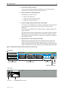
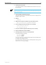
Figure 2: DC Power inlet terminals on an AT-8724XL.
The Fault LED should flash for approximately 10 seconds as the switch
runs internal tests. If the LED continues to flash or remains lit, refer to the
AT-8700XL Series Hardware Reference for troubleshooting information.
10. Check that the Power LED on the switch’s front panel lights green
If the LED fails to light, refer to the AT-8700XL Series Hardware Reference for
troubleshooting information.
11. Connect the Redundant Power Supply (Optional)
AC models of AT-8700XL Series switches have a Redundant Power Supply
(RPS) connector on their rear panel.
The switch is designed to operate with the AT-RPS8000 RPS, which can be
purchased separately. Contact your authorised Allied Telesyn distributer
or reseller for more information.
12. Connect the data cables
Make sure each cable connection is secure. The switch will now perform
basic Layer 2 switching functions.
Configuring the Switch
Some configuration is necessary if you wish to enable the switch’s advanced
switching capabilities. The switch can be configured via the Command Line
Interface (CLI) or Graphical User Interface (GUI).
Using the CLI to configure a switch
1. Connect a terminal or PC to the Terminal Port (ASYN0)
Using the supplied RS-232 DB9 straight-through cable, connect your
terminal or PC to the RS-232 Terminal Port on the switch’s front panel.
2. Set the communication parameters
Set the communication parameters on your terminal or terminal emulation
program to:
• Baud rate: 9600
• Data bits: 8
•Parity: None
• Stop bits: 1
• Flow control: Hardware
38-75VDC , 2A
FOR CENTRALIZED DC
POWER CONNECTION,
INSTALL ONLY IN A
RESTRICTED AREA
DC Power inlet
DC INPUT