


Quick Install Guide 5
C613-04042-01 REV D
5. Install uplink modules (optional)
If you purchased uplink modules, install them now by following the
instructions in the Uplink Module Quick Install Guide.
6. Place the switch in its operating location
If installing the switch in a rack:
• Remove the rubber feet.
• Attach the rack-mounting brackets.
• Mount the switch in the rack.
7. Check the supply voltage and the switch’s rated voltage
AC versions of AT-8700XL Series switches are fitted with a universal main
power supply that will function over the range 100–240 VAC and
50–60 Hz.
DC versions of AT-8700XL Series switches require a supply voltage in the
range 39–60V DC.
The specific power supply requirements for a particular model are clearly
displayed on the rear or underside of the switch. If the supply is outside
the accepted range for the switch, the switch may not operate or damage to
the switch may result.
8. Apply AC power to the switch (for AC models)
Plug the power cord into the AC power connector on the switch’s rear
panel. The Fault LED should flash for approximately 10 seconds as the
switch runs internal tests. If the LED continues to flash or remains lit, refer
to the AT-8700XL Series Hardware Reference for troubleshooting information.
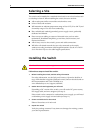
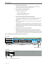
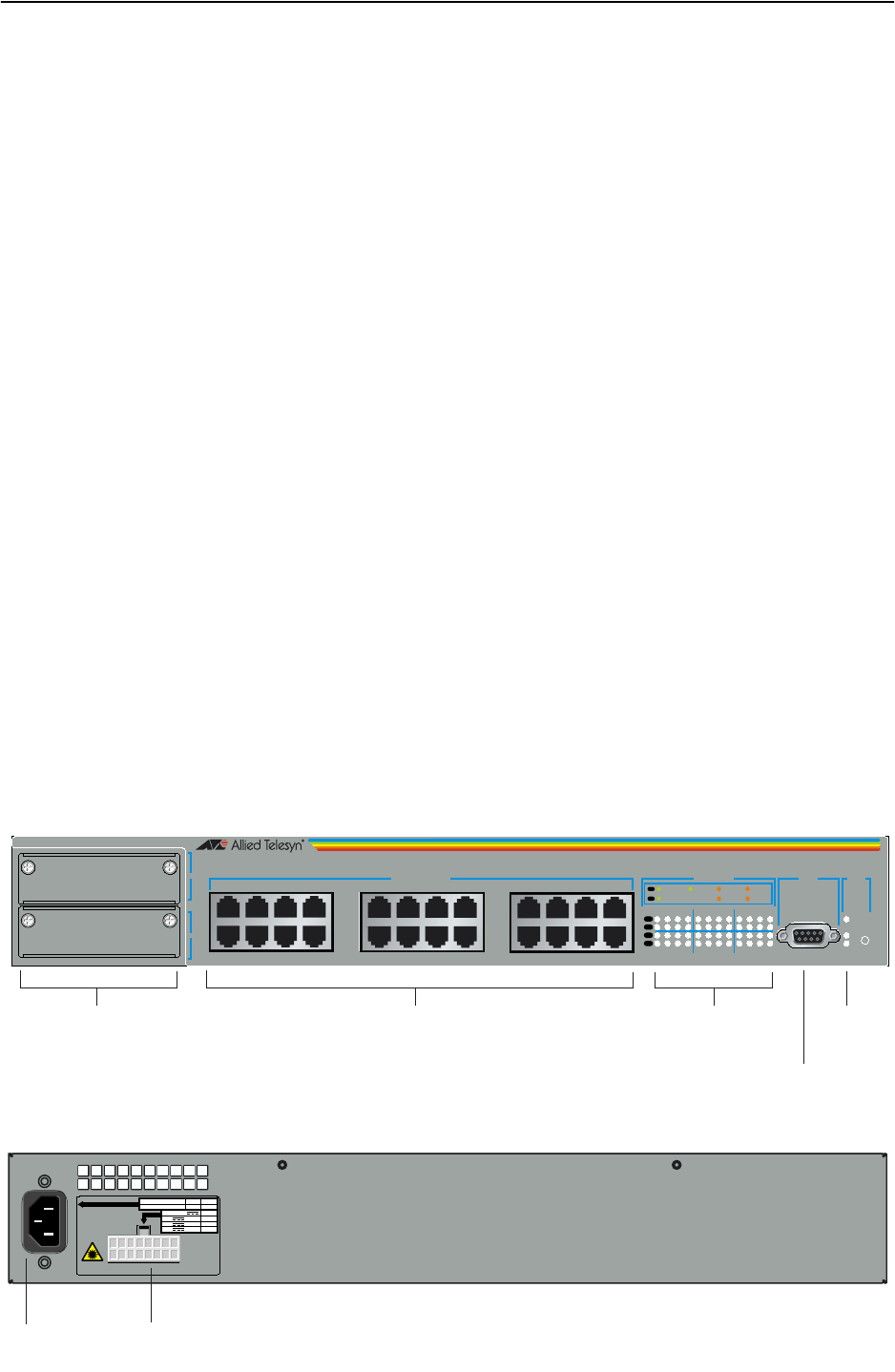
Figure 1: AT-8724XL front panel and rear panel with AC power inlet.
CLASS 1
LASER
R.P.S.
INPUT
AC SUPPLY DATA
100-120/200-240
~
HZ
50/60
AMPS
4/2
Input Vdc
+3.3
+5
+12
A Max
13
8
1
AC Power AT-RPS8000 RPS Connector
STATUS
RESET
FAU LT
PWR
RPS
1
2
3
4
5
6
7
8
9
10
11
12
13
14
15
16
17
18
19
20
21
22
23
24
10BASE-T / 100BASE-TX
1X 3X 5X 7X
2X 4X 6X 8X
9X 11X 13X 15X
10X 12X 14X 16X
17X 19X 21X 23X
18X 20X 22X
100M LINK / ACTIVITY
24X
25
26
RS-232
TERMINAL PORT
10M LINK / ACTIVITY
HALF DUP/
COL
FULL DUP
PORT ACTIVITY
L/A
L/A
D/C
D/C
L/A
D/C
ASYN0
AT-8724XL
Advanced Fast Ethernet Switch
Uplink Module Bays 10/100 BASE Ports Port LEDs System
LEDs
RS-232 Terminal Port
Rear panel
Front panel