


Page 108 | AlliedWare™ OS How To Note: IGMP
Appendix: STP state > Switch
1
Appendix: STP state
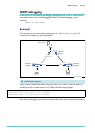
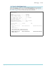
In most of the examples in this document, the switches are configured in a loop and are all in
the same VLAN. To prevent packets from looping the network, STP is configured. The STP
state on each switch is given in the following output screens.
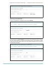
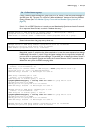
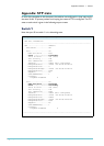
Switch 1
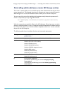
Note that port 50 on switch
1
is in a discarding state.
Manager Switch 1> show stp=default port=49-50
STP Port Information
------------------------------------------------------------------------
STP ..................... default
STP Status ............ ON
Port .................. 49
RSTP Port Role ...... Root
State ............... Forwarding
Point To Point ...... Yes (Auto)
Port Priority ....... 128
Port Identifier ..... 8031
Pathcost ............ 20000 (auto configured)
Designated Root ..... 32768 : 00-00-cd-01-4b-10
Designated Cost ..... 0
Designated Bridge ... 32768 : 00-00-cd-01-4b-10
Designated Port ..... 801a
EdgePort ............ No
VLAN membership ..... 1
Counters:
Loopback Disabled 0
Port .................. 50
RSTP Port Role ...... Alternate
State ............... Discarding
Point To Point ...... Yes (Auto)
Port Priority ....... 128
Port Identifier ..... 8032
Pathcost ............ 20000 (auto configured)
Designated Root ..... 32768 : 00-00-cd-01-4b-10
Designated Cost ..... 20000
Designated Bridge ... 32768 : 00-00-cd-02-e5-40
Designated Port ..... 801a
EdgePort ............ No
VLAN membership ..... 1
Counters:
Loopback Disabled 0
------------------------------------------------------------------------