


AT-RPS3000 Redundant Power Supply Installation Guide
43
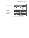
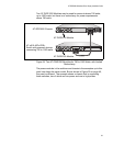
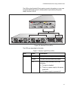
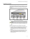
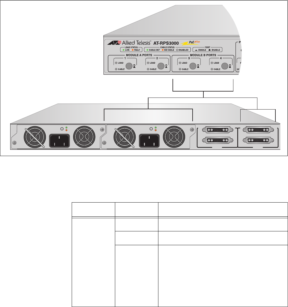
The LEDs in the Module B Ports section provide information you may use
to monitor RPS ports 3 and 4, whose power is provided by the power
supply module in slot B.
Figure 28. Module B Ports LEDs
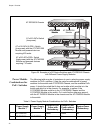
The LEDs are described in this table.
B
B
1
2
3
4
SYSTEM
PoE+ / SYSTEM PoE+ / SYSTEM
SYSTEM
MODULE B
MODULE A
A
A
AT-PWR800
DC OUT
FAULT
100-240 VAC~12A MAX
AT-PWR800
DC OUT
FAULT
2157
100-240 VAC~12A MAX
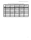
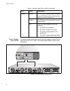
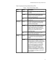
Table 6. Module A and B Ports LEDs
LED State Description
LOAD Green The port is operating normally.
Amber The port has encountered a problem.
Off This LED state indicates one of the
following:
The port is disabled.
There is no power supply in the power
supply slot.
The power supply is powered off.