


Chapter 3: Removing Power Supply Modules
80
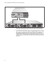
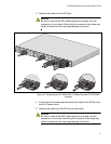
3. Loosen the two captive screws securing the power module to the
chassis.
Figure 60. Loosening the Two Captive Screws
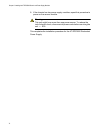
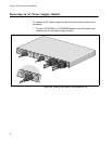
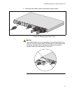
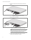
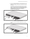
4. Slide the module from the chassis.
Figure 61. Removing the Power Supply from the Chassis
Note
Use care when pulling the power supply module from the chassis.
You might bend the power and control pins on the backplane
connectors if you roughly pull the module from the unit.
5. To install a new power supply module, perform the procedure
“Installing a Power Supply Module” on page 61.
B
B
1
2
3
4
SYSTEM
PoE+ /
SY
ST
EM
Po
E
+ /
SY
STE
M
SYSTEM
MODULE B
MODULE A
A
A
AT-PWR800
DC
O
UT
FA
ULT
AT-PWR800
D
C OUT
FA
ULT
1
0
0
-2
4
0
V
A
C
~
1
2
A
M
A
X
2171
10
0
-2
4
0
V
A
C
~1
2
A
M
A
X
B
B
1
2
3
4
SYST
EM
PoE+ /
SY
STEM
PoE+ /
S
Y
STEM
SYSTEM
MODULE B
MODULE A
A
A
AT-PWR800
D
C OUT
FAU
LT
1
0
0-
24
0
V
A
C
~
12
A
M
A
X
AT-PWR800
DC
OU
T
FA
ULT
2172
10
0-
24
0
V
A
C
~
12
A
M
A
X