


AT-RPS3000 Redundant Power Supply Installation Guide
55
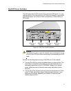
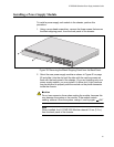
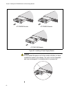
Note
The AT-RPS3000 Chassis is connected to an x610 Series switch
with the AT-RPS-CBL1.0 cable. The cable must be purchased
separately. You will need one cable for each x610 Series switch.
Power Supply
Modules
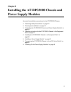
Refer to this table to verify the items in the shipping containers of the
power supply modules.
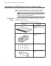
One AT-PNL800/1200
Blank Panel
Blank shipping panel (pre-
installed on the power
supply slots on the back
panel)
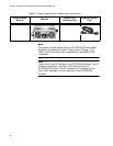
Table 9. AT-RPS3000 Chassis Components
Component Description
AT-PNL800/1200
2160
2189
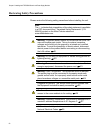
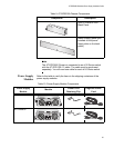
Table 10. Power Supply Module Components
Power Supply
Module
Module
Power Cord
Retaining Clip
Regional Power
Cord
AT-PWR250
AT-PWR800
2185
AT-PWR250
100-240VAC~ 5A MAX
DC OUT
FAU LT
2184
157
2186
AT-PWR800
100-240VAC~ 12A MAX
DC OUT
FAU LT
2184
157