


AT-RPS3000 Redundant Power Supply Installation Guide
71
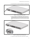
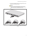
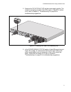
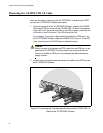
5. Examine the DC OUT/FAULT LED on the power supply module. The
module is operating normally if the LED is green. If the LED is amber
or off, refer to Chapter 4, “Troubleshooting” on page 83 for
troubleshooting suggestions.
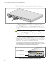
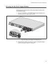
Figure 53. Lowering the Power Cord Retaining Clip
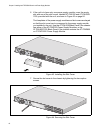
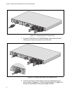
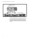
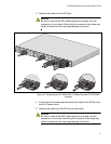
6. In the POWER MODULE STATUS section of the LED panel shown in
Figure 54 on page 72, examine the FAN and DC OUT LEDs of the
power supply module you just powered on. Both LEDs should be
green. If the LEDs are amber or off, refer to Chapter 4,
“Troubleshooting” on page 83 for troubleshooting suggestions.
B
B
1
2
3
4
SYSTEM
PoE+ /
SYSTEM PoE+ /
SYSTEM
SYSTEM
M
O
D
U
L
E
B
M
O
D
U
L
E
A
A
A
AT-PWR800
DC OUT
FAULT
AT-PWR800
DC OUT
FAULT
2147
100-240 VAC
~12A
MAX
100-240
VAC
~12A
MAX
D
C
O
U
T
F
A
U
L
T
1
0
0
-2
4
0
V
A
C
~
1
2
A
M
A
X