


AT-RPS3000 Redundant Power Supply Installation Guide
67
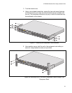
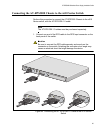
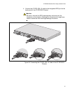
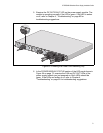
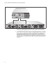
4. Connect the AT-RPS-CBL1.0 cable to the designated RPS port on the
back panel of the AT-RPS3000 Chassis.
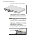
Caution
Be sure to connect the RPS cable squarely and evenly on the
connector on the chassis. Attaching the connector at an angle may
cause an electrical short that might damage the device.
Figure 48. Connecting the AT-RPS-CBL1.0 Cable to the AT-RPS3000
Chassis
B
B
1
2
3
4
SYSTEM
P
oE+ /
SYSTEM PoE
+
/
SYSTEM
SYSTEM
MODULE B
MODULE
A
A
A
AT-PWR800
DC
O
U
T
F
AU
LT
AT-PWR800
DC O
U
T
FAU
LT
B
B
1
2
SY
S
TE
M
P
o
E
+
/
S
Y
S
T
E
M
P
o
M
M
O
D
U
L
E
A
B
B
1
2
S
Y
S
T
E
M
P
o
E
+
/
S
Y
S
T
E
M
P
o
M
M
O
D
U
L
E
A
2145
B
B
1
2
S
Y
S
T
E
M
P
o
E
+
/
S
Y
S
T
E
M
P
o
M
M
O
D
U
LE
A
100-240 VAC
~12A
MAX
100-240
VAC
~12A
MAX