


AT-S63 Management Software Features Guide
Section II: Advanced Operations 191
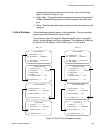
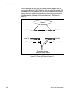
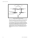
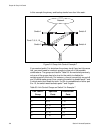
But if the failure occurred further upstream between switches 1 and 3, the
server would not detect the problem. Unaware of the problem, it would
lose connectivity to the network because it would continue to transmit
packets to switch 3, which would discard the packets. This is shown in this
figure.
Figure 19. Group Link Control Example 2
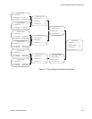
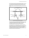
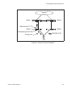
With group link control you can address this problem by creating on switch
3 a group of the two ports that connect to switch 1 and the server. Thus,
any change to the link state of the port connected to switch 1 is
automatically transferred to the port connected to the server.
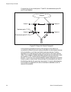
Assume that switch 3 is connected to switch 1 with port 17 and to the
server with port 24. Port 17 would be the upstream or control port and port
24 would be the downstream port. When the two ports are grouped
together, the switch reacts to a loss of the link on port 17 by disabling port
24, dropping the connection to the server. The server, having lost
connectivity to switch 3, would respond by activating its alternate network
interface and transferring the traffic to switch 4.
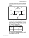
Switch 1
Network
Switch 3
Switch 2
Switch 4
Primary link
Secondary link