


Chapter 25: Spanning Tree and Rapid Spanning Tree Protocols
284 Section V: Spanning Tree Protocols
This feature is supported on the base ports of the switch as well as on any
expansion modules and fiber optic transceivers installed in the unit.
This feature is not supported in STP or MSTP. It is also not supported on
RSTP edge ports.
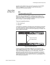
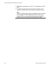
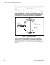
The following figures illustrate this feature. The first figure shows RSTP
under normal operations in a network of three switches that have been
connected to form a loop. To block the loop, switch 3 designates port 14
as an alternate port and places it in the blocking or discarding state.
Figure 37. Loop Guard Example 1
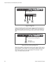
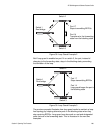
If port 17 on switch 2 stops transmitting BPDUs, port 14 on switch 3
transitions from the blocking state to the forwarding state because the
switch assumes that the device connected to the port is no longer an
RSTP device. The result is a network loop, as illustrated in Figure 38 on
page 285.
Switch 3
Switch 2
Switch 1
Root bridge
Port 17
Forwarding state
Port 14
Blocking state