


15
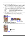
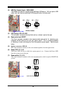
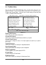
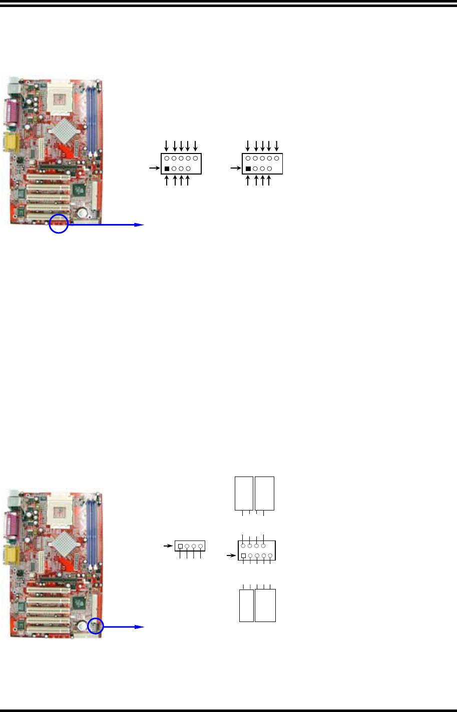
(2) USB Port Header (9-pin) : USB1/USB2
The headers are used for connecting the additional USB device. With an option USB
cable, your can have two additional USB plugs affixed to the back panel.
USB Port Headers
Pin 1
USB2
VCC
-
DATA
GND
+DATA
VCC
OC
-
DATA
GND
+DATA
Pin 1
USB1
VCC
-
DATA
GND
+DATA
VCC
OC
-
DATA
GND
+DATA
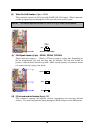
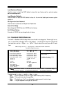
(3) IDE Activity LED: HD LED
This connector connects to the hard disk activity indicator light on the case.
(4) Reset switch lead: RESET
This 2-pin connector connects to the case-mounted reset switch for rebooting your
computer without having to turn off your power switch. This is a preferred method
of rebooting in order to prolong the life of the system’s power supply. See the figure
below.
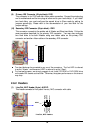
(5)
Speaker connector: SPEAK
This 4-pin connector connects to the case-mounted speaker. See the figure below.
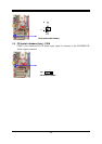
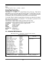
(6) Power LED
: PW_LED
The Power LED will be on while the system power is on. Connect the Power LED
from the system case to this pin.
(7) Power switch
: PW_BTN
This 2-pin connector connects to the case-mounted power switch to power ON/OFF the
system.
System Case Connections
HDLED
RESET
VCC5
GND
VCC5
PWR LED
PWRBTN
PWRBTN
PWRLED
HDDLED
RSTSW
NC
GND
FPSPEAK
SPKR
GND
NC
VCC5
Pin 1
Pin 1