15
setting its jumpers accordingly. Please refer to the documentation of your hard disk for
the jumper settings.
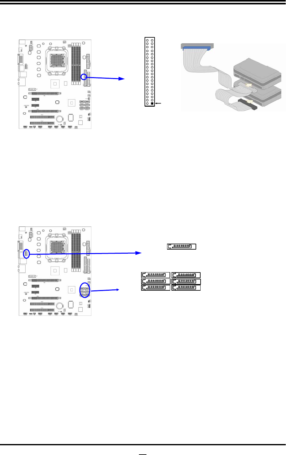
Primary IDE Connector
Pin 1
IDE1
•
Two hard disks can be connected to each connector. The first HDD is referred to as the
“Master” and the second HDD is referred to as the “Slave”.
•
For performance issues, we strongly suggest you don’t install a CD-ROM or DVD-ROM
drive on the same IDE channel as a hard disk. Otherwise, the system performance on this
channel may drop.
(10) Serial-ATAII Port connector:
SATA1~SATA6; E-SATA1
(optional)
This connector supports the provided Serial ATA2 IDE hard disk cable to connecting
the motherboard with serial ATAII hard disk. E-SATA1 is not for SATA harddrive ,it is
only for connecting to SATAII 1, SATA II 2, SATA3,SATA4,SATA5,SATA6 to let the
ESATA port work.
SATA3
SATA
1
E-SATA1
SATA6
SATA4
SATA5
(11) ESATA Port:
CN1 for ESATA
(optional)
This connector supports the External Serial ATA2 (ESATA) enable the full SATA
interface speed outside the chassis, up to 3Gb/s. The ESATA port can be enabled only
when the E-SATA 1 is connected to one of SATA 1~SATA6.
(12)
D-Sub 15-pin Connector: VGA1
VGA is the 15-pin D-Subminiature female connector; it is for the display devices, such
as the CRT monitor, LCD monitor and so on.
(13) Digital Visual Interface: DVI
This interface standard designed to maximize the visual quality of digital display
devices such as flat panel LCD computer displays and digital projectors.
(14) High-Definition Multimedia Interface: HDMI
This point-to-point interface is for audio and video signals designed as a single-cable
solution for home theater and consumer electronics equipment.


