


English
7
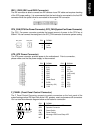
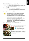
CPU_FAN (CPU Fan Power Connector); SYS_FAN (System Fan Power Connector)
The CPU_Fan power connector provides the largest amount of power to the CPU fan at
600mA. You can connect the casing fan to the SYS_FAN connector to enhance system cooling.
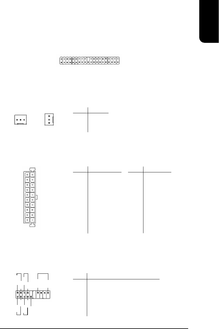
ATX (ATX Power Connector)
The ATX power connector provides power to the motherboard. Prior to connection,
please make sure that the power supply is disconnected.
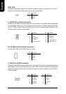
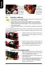
F_PANEL (Front Panel Control Connector)
The F_Panel Control Connector connects to certain connectors on the front panel of the
system casing such as IDE Hard Disk Active LED, speaker, reset, and power on/off connectors.
You can use the schematic diagram below as the basis for connection.
PIN SIGNAL
1 GND
2 +12V
3 Sense
PIN SIGNAL
1 3.3V
2 3.3V
3 GND
4 VCC
5 GND
6 VCC
7 GND
8 Power Good
9 5VSB
(stand by +5V)
10 +12V
PIN SIGNAL
11 3.3V
12 -12V
13 GND
14 PS_ON
(soft on/off)
15 GND
16 GND
17 GND
18 -5V
19 VCC
20 VCC
PIN SIGNAL
HD IDE Hard Disk Active LED
SPK Speaker Connector
RES Reset Switch
PW Power Switch
MSG Message LED/Power/Sleep LED
NC NC
IDE1 / IDE2 (IDE1 and IDE2 Connector)
The IDE connector is able to connect two IDE devices via an IDE cable and requires checking
of the IDE jumper setting. It is recommended that the hard drive be connected to the first IDE
connector while the optical drive be connected to the second IDE connector.
CPU_FAN SYS_FAN
1 39
2
40
1
1
20
11
10
1
1
2
19
20
HD-
HD+
RES+
RES-
NC
SPK-
MSG-
MSG+
PW-
PW+
SPK+