


8
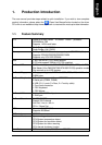
English
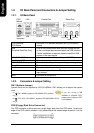
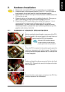
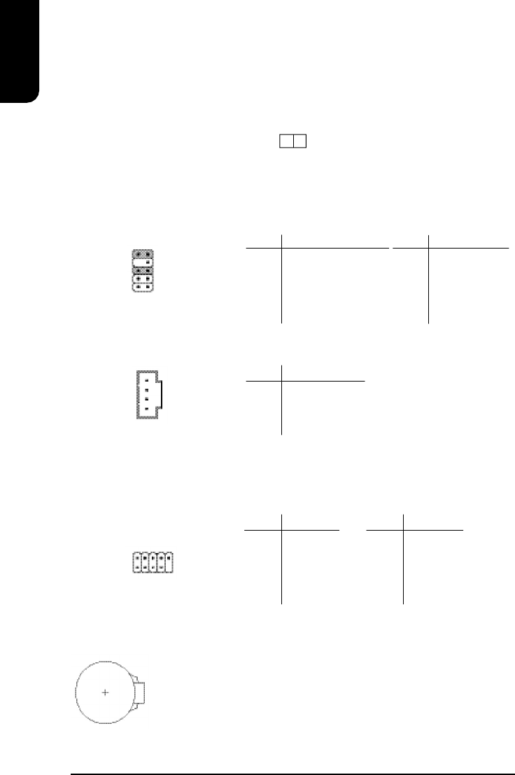
F_AUDIO (Front Audio Connector)
Connects to the audio connector located on the front panel of the system casing (dependent
on case design). When use of the front panel audio connector is required, please remove the
5-6 pin, 9-10pin jumper. Please note that use of only the front panel audio connector or the
rear panel audio connector is permitted.
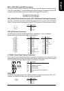
CD_IN (Optical Drive Audio Connector)
Connects CD-ROM or DVD-ROM audio connector.
PIN SIGNAL
1 CD_L
2 GND
3 GND
4 CD_R
RAM_LED
When the RAM_LED is lit, please do not remove the memory since there is still power being
supplied to the component. Short circuiting or hardware damage may occur if memory is
removed with the RAM_LED is still lit. Please remove the power plug before removing the
memory.
+
_
1
10
9
2
1
PIN SIGNAL
1 MIC
2 GND
3 MIC_BIAS
4 POWER
5 Front Audio (R)
PIN SIGNAL
6 Rear Audio (R)
7 Reserved
8 NO PIN
9 Front Audio (L)
10 Rear Audio (L)
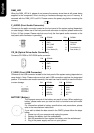
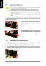
F_USB1 (Front USB Connector)
Connects to the USB connector located on the front panel of the system casing (dependent on
case design). Note: Please make sure that each USB connection matches its designated
position. If connections are made incorrectly, the result can lead to inability to use the function
or even damage.
PIN SIGNAL
6 USB Dy+
7 GND
8 GND
9 NO PIN
10 NC
PIN SIGNAL
1 POWER
2 POWER
3 USB Dx-
4 USB Dy-
5 USB Dx+
2
10
1 9
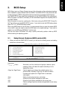
The improper removal of the battery can result in harm. When replacing a
battery, please make sure you use one that is of similar brand and model
number.
For information related to battery specifications and precautions, please
refer to the manufacturer instructions.
If you wish to delete the data stored in the CMOS, please follow the steps
below:
1. Please turn off your computer and unplug the power.
2. Remove the battery from the motherboard.
3. Wait 30 seconds and then replace the battery onto the motherboard.
4. Plug in the power supply and turn on your system.
BATTERY (Battery)