


DN1726-0811
19
KT-400 Ethernet Four-Door Controller Installation Manual
Installing the KT-400 Ethernet Four-Door Controller
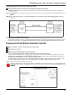
Preparing to Install the KT-400 Ethernet Four-Door Controller
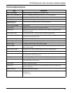
Required to install KT-400 Ethernet Four-Door Controller
• For North America: AC transformer 120 VAC 60 Hz IN; 16 VAC, 75 VA OUT; class 2 (not included)
• One battery 12 VDC, 7 Ah (not included)
• Ground clamp (not included)
A visual inspection should be made when unpacking the KT-400 Ethernet Four-Door Controller. Any missing item/part or
damaged component should be reported immediately.
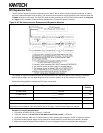
Physical Installation
Check for ideal indoor location
Stay away from electrical or communication devices
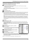
The KT-400 cabinet has been designed to be mounted on a wall without any additional enclosures. The cabinet is large
enough to accommodate the battery backup supply and the necessary wiring connections for most applications. EMT
(Electrical Metallic Tubing) conduit knockouts are provided in 1.9 cm (0.75 in) on all sides of the cabinet.
The cabinet should be mounted indoors, in a secure location providing normal temperature and humidity, leaving 23 cm
(8 in) clear space around all sides and a minimum of 33 cm (13 in) clear space in front of the cabinet. The location should
be easily accessible for servicing the equipment and it is recommended that controllers be located close to the controlled
doors.
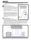
Controllers must be located at a minimum distance of 2 m (6 ft) from any high voltage equipment or wiring and from
electrical equipment susceptible of generating electrical interference, at a minimum distance of 1 m (3 ft) from telephone
equipment or lines, and at a minimum of 8 m (25 ft) from any transmitting equipment. Physical access, using keys, on
controlled doors must be provided so that the KT-400 Ethernet Four-Door Controller can easily be accessed for servicing
in case of malfunction.
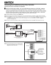
Earth Grounding
AWG #18 grounding wire to EGND
Since the KT-400 Ethernet Four-Door Controller uses high performance communication, proper grounding must be
provided to ensure proper operation.
An AWG #18 single conductor copper wire must be used to ground each controller to good earth ground as
per the local electrical code (be careful with ground loops). The ground clamp should be located below any
other ground.
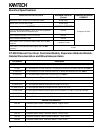
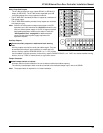
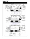
Door Locking Devices
Connect the door lock device to + and LK1-, (+ and LK2-),
(+ and LK3-) or (+ and LK4-)
Note: If you need additional power for ALL the external locks, you can use an
external +power supply. Connect the power supply to the VIN and GND
terminals and put jumper JP4 on EXT.
When jumper JP4 is on INT, the total maximum current draw is
1 Amp for KT-400 at 12 to 13.75 VDC, or
When jumper JP4 is on EXT, the total maximum current draw is
3 Amps at 12 to 28 VDC
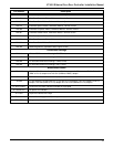
Check for local “magnetic lock” regulations
LK1-, LK2-, LK3- and LK4- and + terminals are located near the battery
(BATT) terminals. The locking device outputs are controlled according to the end-user programmed parameters for
allowing access to or unlocking doors according to schedules and access levels. These doors locking device outputs can
operate DC powered locking devices such as electromechanical strikes and can be configured to operate fail-safe or fail-
secure (normal or reverse action).
Note: Use 1 K ohm EOL (End-of-Line resistor) between + and LK- terminals if not used.