


DN1726-0811
25
KT-400 Ethernet Four-Door Controller Installation Manual
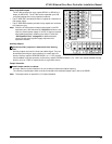
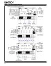
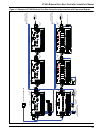
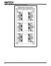
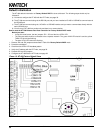
Important Installation Rules about Expansion Modules
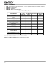
Note 1: The maximum current draw must be calculate each time there is a new module added to the SPI chain.
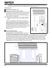
Rule 2: The SPI cable, between the KT-400 and the 1st module or between each modules, cannot exceed 1 m (3 ft). Shielded
wire should only be used in areas with excessive RF noise of electromagnetic interference. Keep in mind that the
expansion modules must be defined in the EntraPass system when they are installed.
Rule 3: There is already 4 relays available on the KT-400 Ethernet Four-Door Controller. Don't forget to check the relays
number assignments to prevent redundancy unless it has been planned on purpose.
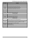
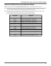
For more details concerning the expansion modules, refer to the following documents:
Part number Description
DN1775 KT-MOD-INP16 Install Sheet - French version
DN1776 KT-MOD-INP16 Install Sheet - English version
DN1780 KT-MOD-OUT16 Install Sheet - French version
DN1781 KT-MOD-OUT16 Install Sheet - English version
DN1785 KT-MOD-REL8 Install Sheet - French version
DN1786 KT-MOD-REL8 Install Sheet - English version
DN1805 KT-MOD-CAB Install Sheet - French version
DN1806 KT-MOD-CAB Install Sheet - English version
DN1790 Expansion Modules Dimensions Drawing in DWG format
DN1791 Expansion Modules Dimensions Drawing in PDF format
DN1792 KT-MOD-CAB Dimensions Drawing in DWG Format
DN1793 KT-MOD-CAB Dimensions Drawing in PDF Format