


DN1726-0811
20
Warning: Controlled door locks may be governed by regulatory bodies and should always be installed according to local
regulations. In most instances, there are strict limitations to installing fail-secure devices and fail-safe locking devices
such as magnetic locks or other similar locking devices on doors used as emergency exits.
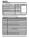
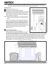
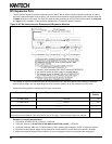
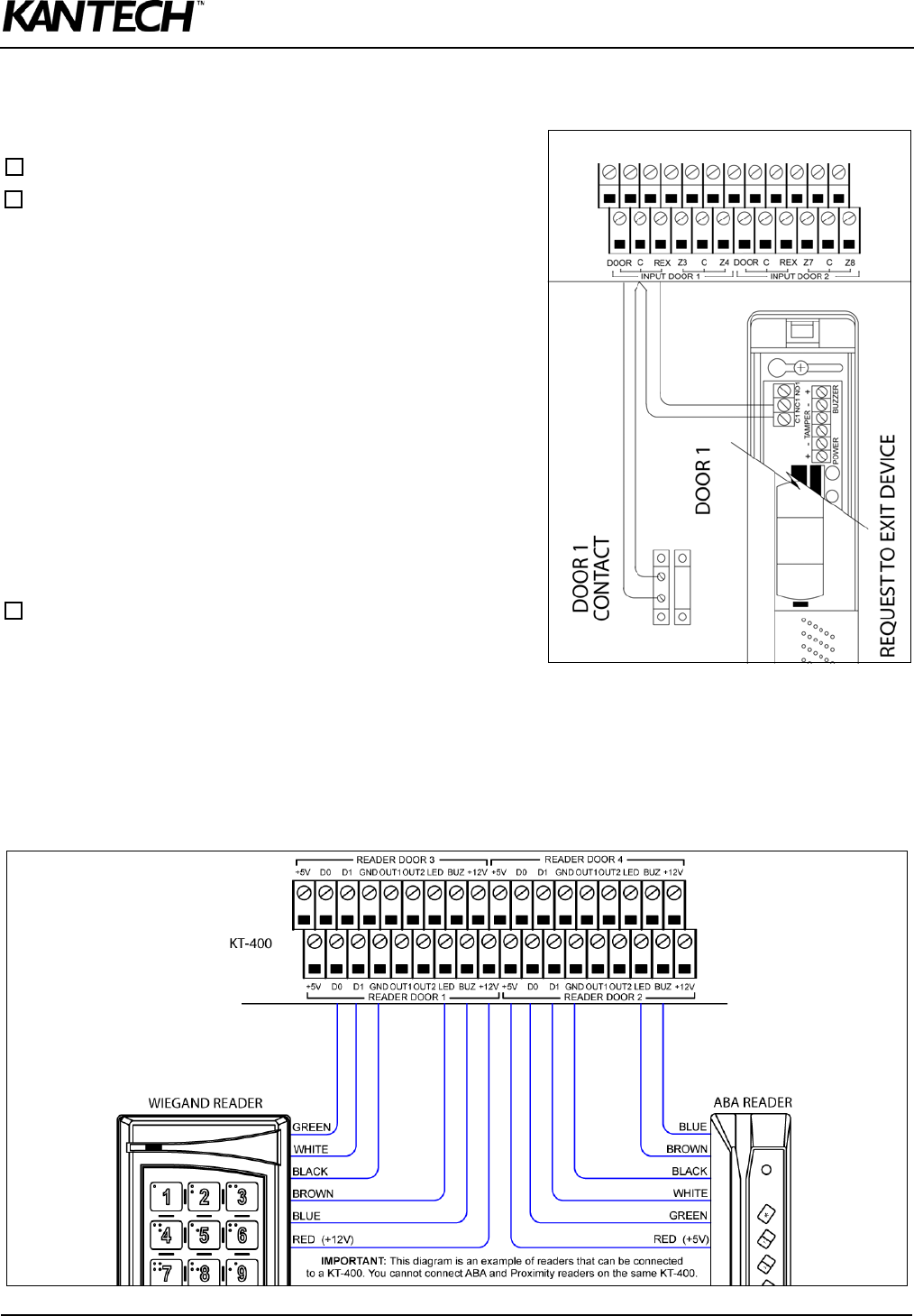
Hooking Up Inputs
Connect devices to inputs 1 to 16
Resistors for all inputs 5.6K ohm (if selected)
The KT-400 has an on-board capability of monitoring 16 input points
(expandable to 256 with expansion modules). Each onboard input is
supervised with or without end-of-line resistors (5.6K ohm). The
maximum distance of one line is 600 m (2,000 ft) with AWG #22 in a
single or double EOL configuration.
Note: Onboard Inputs can be defined with: none, single or double EOL
(End-of-Line) resistor(s) according to your EntraPass software
settings.
Inputs 1-2 are automatically reserved for the first controlled door.
The contact is assigned input 1 and the associated request-to-exit
detector as input 2. Inputs 5 and 6 are automatically reserved for the
second controlled door. The contact is assigned input 5 and the
associated request-to-exit detector as input 6. Inputs 9 and 10 are
automatically reserved for the third controlled door. Inputs 13 and 14
are automatically reserved for the fourth controlled door. There is no
obligation to follow these rules but this standard convention
facilitates servicing.
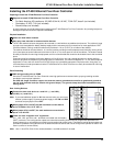
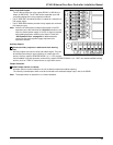
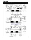
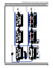
Connect readers and keypads
READER CONNECTION TERMINAL WARNING
Connecting the red wire lead (or power lead) of a 5 VDC reader to
the 12 VDC terminal may damage the reader. See your reader
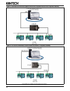
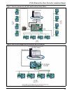
installation procedure for proper power connection. Up to 4 readers can be connected to a KT-400. They can be installed
on one door to control both entry and exit or on four separate doors operating independently to control one-way access.
The distance between the readers and the KT-400 varies by reader type (please consult the installation manual for
details). Auxiliary outputs provide visual and/or audible access operation feedback at the controlled door. Outputs
“READER DOOR 1 - OUT1 OUT2 LED & BUZ” are used for the first door, “READER DOOR 2 - OUT1 OUT2 LED &
BUZ” are used for the second door, “READER DOOR 3 - OUT1 OUT2 LED & BUZ” are used for the third door and
“READER DOOR 4 - OUT1 OUT2 LED & BUZ” are used for the fourth door.