


DN1726-0811
37
KT-400 Ethernet Four-Door Controller Installation Manual
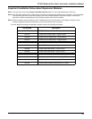
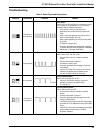
Installation Checklist
To the Installer: If you are familiar with the installation, you can use the checklist with the symbol.
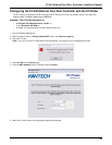
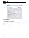
Installing the KT-400 Ethernet Four-Door Controller
Preparing to install the KT-400 Ethernet Four-Door Controller
Required to install KT-400 Ethernet Four-Door Controller
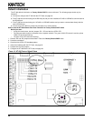
Physical Installation
Check for ideal indoor location
Stay away from electrical or communication devices
Earth Grounding
AWG#18 grounding wire to EGND
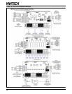
Door Locking Devices
Connect the door locked device to + and LK1-, (+ and LK2-), (+ and LK3-), or (+ and LK4-)
When jumper JP4 on INT (internal), the maximum current draw is 1 Amp at 12 to 13.75 VDC, or
When jumper JP4 on EXT (external), the maximum current draw is 3 Amps at 12 to 28 VDC
Check for local “magnetic lock” regulations
Hooking Up Inputs
Connect devices to inputs 1 to 16
Resistors for all inputs 5.6K ohm (if necessary)
Connect readers and keypads
Auxiliary Outputs
Connect auxiliary outputs to readers and local warning devices
Tamper Protection
Install tamper switch on cabinet
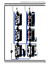
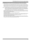
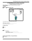
Connecting the KT-400 Ethernet Four-Door Controller
Connecting the VC-485 or the USB-485 to the RS-485 Bus
Connect the RS-485 cable to (COM1) +485- and the RS-485 signal ground to the 12 VDC AUX - (negative)
Connecting the Master Controller to the Host PC
Connect the RS-232 flat cable from the KT-400 to the PC
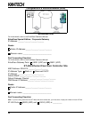
Connecting Expansion Modules to the KT-400 SPI Expansion Port
Make sure input and output expansion modules are not in the same SPI group
Calculate maximum current draw and connect external power supply(ies) to expansion module(s), if required
Make sure the power jumper on the modules is in the correct position when using external power supply(ies)
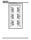
Powering the KT-400 Ethernet Four-Door Controller (for North America only)
Install 120 VAC IN / 16 VAC, 75 VA OUT, class 2 transformer
Place battery in cabinet
Power up the KT-400 Ethernet Four-Door Controller