


Installation—Accessories
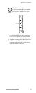
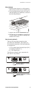
8 Temperature/Humidity Module
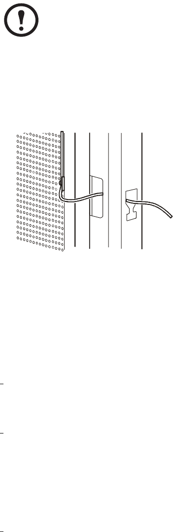
7. With the door fully open, thread the sensor
cords through the opening in the front post of
the rack.
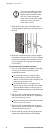
8. Route the cords between the vertical support
rail and the side panel. Each 13-ft (4-m) sensor
cord may be extended to a maximum of 50 ft
(15 m), using RJ-45 couplings and standard
CAT5 cables.
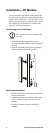
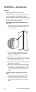
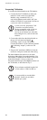
To install sensors in another location:
1. Use one of the following methods, depending
on the type of surface on which you are
mounting the sensor:
To mount the sensor on a wall or other
smooth surface, peel the backing off the
adhesive of the sensor mount, and place the
sensor mount onto the wall.
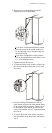
To mount the sensor on a rough wall or
porous surface, first install the wall anchor.
Then attach the adhesive sensor mount to
the wall anchor using the provided flat-head
screw.
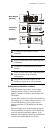
2. Thread a wire tie through the sensor mount,
and secure the sensor with the tie. Tighten the
wire tie and trim any excess.
Neatly route the sensor cord and connect the
sensor to the APC device.
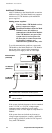
3. Thread a wire tie through the sensor mount,
and secure the sensor with the tie. Tighten the
wire tie and trim any excess.
4. Neatly route the sensor cord and connect the
sensor to the Main Module or TH Module.
Note
If you use more than one sensor
per rack, route the sensor cord
farthest from the middle of the
rack first. When routing the
sensor cord closest to the middle
of the rack, secure all sensor
cords in the wire tie.
aem0076a