


INSTALLATION
w
w
w
.apc.com
®
Back-UPS HS 500
User’s Manual
990-9236 3/04
3
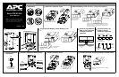
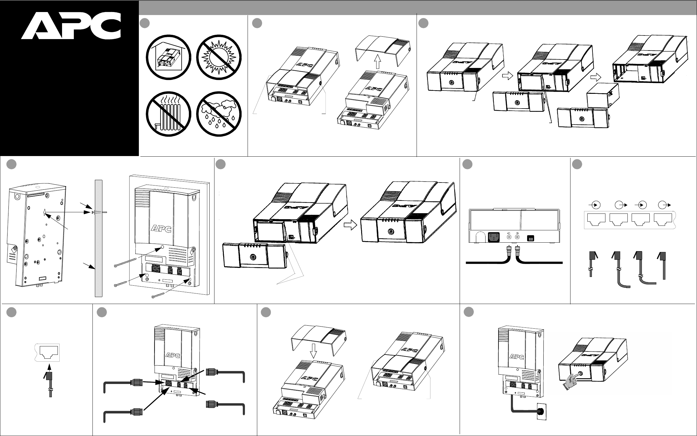
Remove Battery (if wall-mounting - if not proceed at Step 5)
0 - 40
o
C (32 - 104
o
F)
1
Placement
2
Remove Connector Cover
Disconnect battery
wires from battery.
Remove battery.
Press cover release
tab (one each side)
and remove cover.
Caution: To prevent damage to the ribbon cable (not shown)
that connects the cover to the UPS, replace the cover after
removing the battery. Do not disconnect the ribbon cable
from the cover or the UPS.
Press the outlet cover release
tab (one each side); and pivot
cover off the unit.
Phone Line Out
4
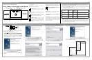
Mount Back-UPS (optional)
Wall Anchor
Mounting
Hole
Wall
5
Connect/Install Battery, Install Battery Cover
Install battery cover.
Connect and install
the battery.
Press the outlet cover
release tab (one each
side); and pivot cover
off the unit.
6
Connect Cable Modem,
Circuit Breaker
Push to Reset
Cable Out
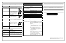
Input:
230V~, 2.2A, 50-60Hz
Cable In
From Cable Provider
(Phone, Internet,
and/or CATV; or
DSS)
To Cable Modem,
VCR, DSS or TV
Cable Box
7
Connect Phone Line
LAN
NetworkModem/Phone/Fax
RJ-45
Connectors
(can accept RJ-11)
RJ-45
Connectors
Phone Line In
(Standard or
DSL)
From Network Device
(or Computer Using a
Crossover Cable)
From Modem
DSS or CATV Receiver
8 10
Install Connector Cover
(optional)
or DSL to Surge
Connect Network
Equipment
To Hub
or
Router
11
Connect to Power Source and Switch on UPS Power
Connect Equipment Power Cords
Hub
or Router
Modem
Network Device
Network Device
Output 1
Output 2
Output 3
Output 3
9
to Surge Protection
Protection (optional)
Align the holes in the
cover with the connector
cover release tabs (one
each side) and lower
connector cover.
7 AMP
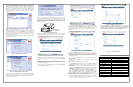
The line cord used for this connection is supplied
by the user.
NOTE: APC recommends your network equipment
(computer, modem, router, hub, or other networked
devices) be completely installed, configured, and
tested prior to adding this UPS to the network.