


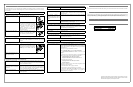
Input Voltage (on line) 180 - 266 Vac
Input Frequency 47 - 63 HZ (autosensing)
Output Wave Form (On battery) Stepped Sine Wave
Maximum Load 500 VA 300 Watts
Operating temperature 32 - 104° F (0 to 40° C)
Storage temperature 5 - 113° F (-15 to 45° C)
Operating humidity 10 - 90% non-condensing
Storage humidity 10 - 95% non-condensing
Physical: (H x W x D) 14.65 x 8.85 x 4.13 in
(37.2 x 22.5 x 10.5 cm)
Weight 16.3 lb (7.4 kg)
Typical Recharge Time 6 - 8 hours
EMI Classification EN50091-2, Class B
Approvals NEMKO-GS, CE, and GOST
Specifications
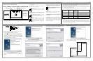
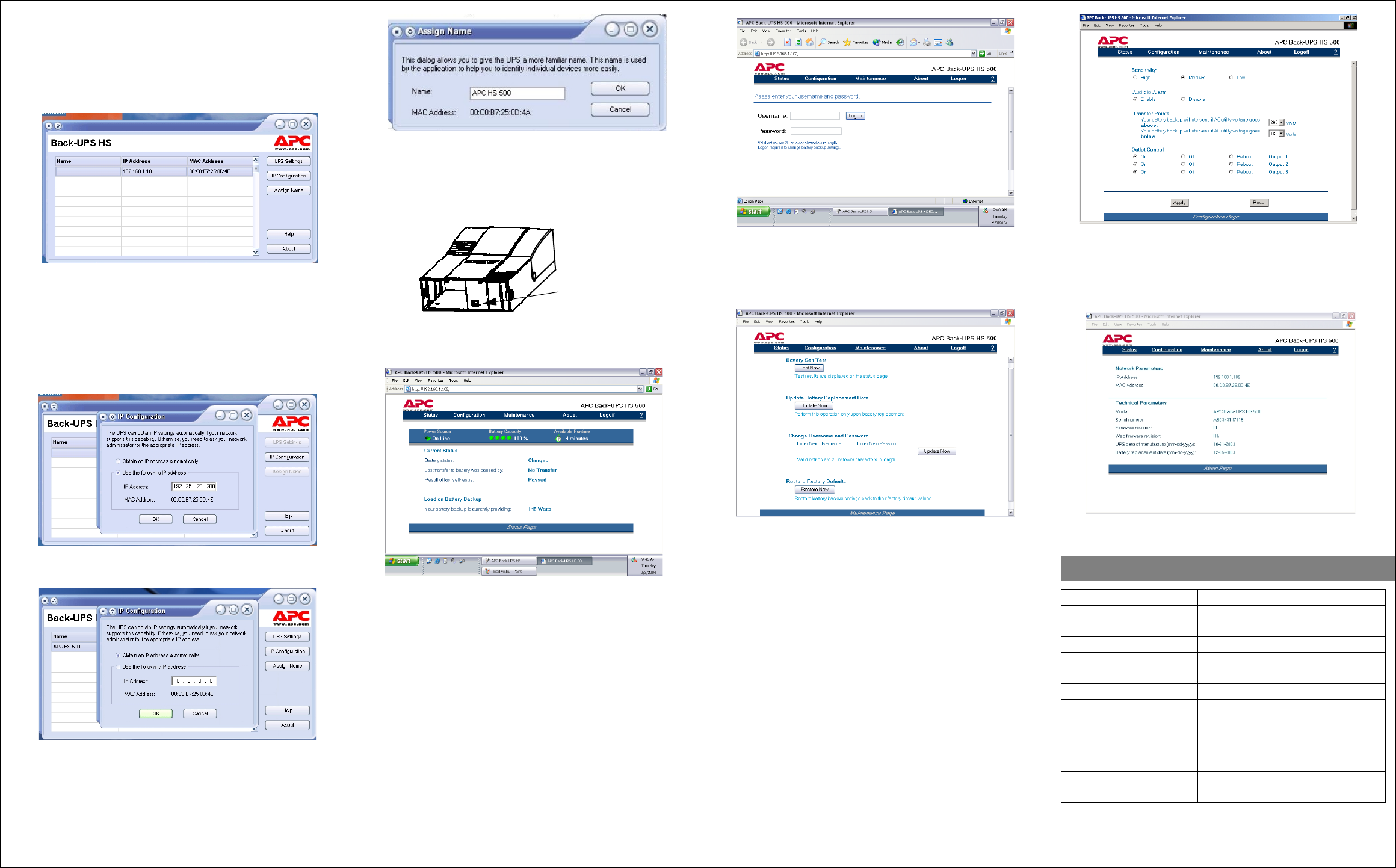
8. Following installation, the Back-UPS HS software is available in the Start
menu. Upon launching the program, it searches for all Back-UPS HS devices on
the network, and will identify them as shown in Figure 8 by IP Address and
MAC Address. The IP Address is automatically assigned to the Back-UPS by
the DHCP services from your hub or router. IP Addresses assigned by the
DHCP service may automatically change over time. Thus, APC recommends
you do not bookmark the IP Address, as you may not be able to access it
through your browser. The MAC Address is assigned to the Back-UPS HS 500
at the factory.
.
Figure 8. Back-UPS HS IP Address and MAC Address Screen
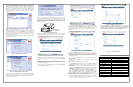
9. If there are no DHCP services on the network, or if you want to assign an IP
Address you can easily remember, you can manually assign an IP Address to
the Back-UPS by clicking on the IP Configuration button. The address you
assign must follow the format shown in Figure 9 and cannot duplicate an
address already assigned. Figure 10 shows the IP Configuration Screen with the
IP Address fields set to zero (0).
To assign an IP Address to your computer, please read and follow the directions
that came with your computer.
Figure 9. Assign IP Address Screen
Figure 10. Blank Assign IP Address Screen
10. You can assign a name to the Back-UPS by clicking on the Assign Name
button (Figure 8) and entering the name in the Assign Name Screen dialog. It
will appear in the column to the left of the IP Address of the device (Figure 11).
Names should not be duplicated.
Figure 11. Assign Name Screen
11. To reset the Back-UPS HS to factory default values, use the UPS Settings
button. If the Back-UPS HS does not reset using the software, remove the
Battery Cover and insert a small object (about 2 inches in length) into the hole
located next to the telephone jack (Figure 12) for approximately 5 seconds.
Note: The telephone jack is provided for factory testing only - do not connect
anything to this jack).
Figure 12. Manual Reset Access
12. Before performing any UPS maintenance task, check the Status of the UPS by
clicking on the Status link. The screen shown in Figure 13 will be displayed.
Figure 13. Back-UPS HS 500 Status Screen
13. To change the configuration of the Back-UPS or perform UPS maintenance,
you must log on to the web page (Figure 11) by clicking on the UPS Settings
button.
When this page is displayed, enter a default Username of apc, and a default
Password of apc. To change the Username or Password, you must log on and
then click Maintenance (Figure 14).
Note: You can also access the Logon Page Screen by entering the IP Address
into the Address line of your browser.
Manual Reset
Access
Figure 14. Log On Screen
14. Using the Maintenance Screen (Figure 15), you can perform a Battery Self-
Test, Update the Battery Replacement Date, Change the User Name or
Password (as previously discussed) then click Update Now, or you can
Restore Factory Defaults. Note: You must be logged on to perform any of
these tasks.
Figure 15. Maintenance Page Screen
15. Using the Configuration Page Screen (Figure 14), you can adjust the
Sensitivity of the Back-UPS. By adjusting the Sensitivity, the Back-UPS will
allow the unit to switch to battery power depending on the quality of the AC
utility power being supplied to the unit. Use of the Sensitivity settings are for
the following conditions:
Low - Use only for extreme conditions of low input voltage. Not recommended
for computer loads.
Medium - Back-UPS frequently goes On Battery due to low input voltage
(recommended).
High - Connected equipment is sensitive to low voltage.
The Configuration Page Screen also allows you to enable or disable the
Audible Alarm. If enabled, this alarm operates as described in the Status
Indicators and Alarms section of this manual. If disabled, the Back-UPS will
quiet the alarm.
Additionally, the Configuration Page Screen allows you to adjust the voltage
Transfer Points. The Back-UPS will transfer to On Battery operation at input
voltages Above or Below the points selected in the drop-down Volts menu.
Finally, the Configuration Page Screen provides Output Control for the four
outlets of the Back-UPS. Control consists of switching power On or Off at
Output 1, Output 2, or the two outlets of Output 3. It also allows you to
Reboot loads by automatically switching power Off and then On at the selected
outlet. If an outlet is switched Off, it cannot be rebooted.
To use the Configuration Page Screen, you must be logged on to the Back-
UPS. Select the desired function and click on the Apply button. To reset the
unit to the factory defaults, click the Reset button.
Figure 16. Configuration Page Screen
16. The About Page Screen provides general information about your Back-UPS
including Network Parameters (IP and MAC Addresses), as well as Technical
Parameters (Model, Serial Number, Firmware Revision, Web Firmware
Revision, UPS Date of Manufacture, and Battery Replacement Date).
Figure 17 About Page Screen