


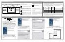
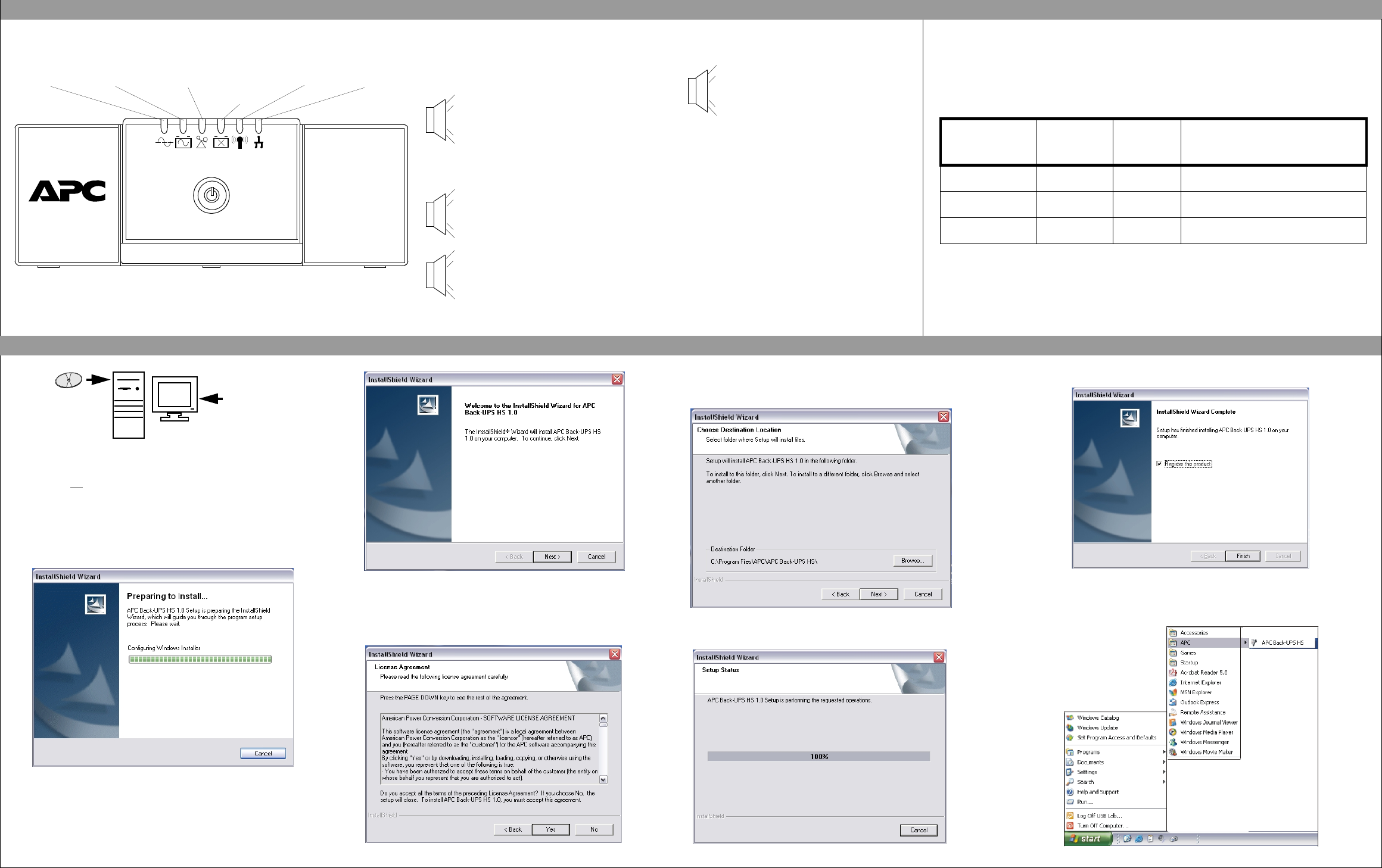
Figure 2. InstallShield Welcome Screen
4. The software will then display the Licence Agreement (Figure 3). Please
read the Agreement and accept the terms by clicking Yes. To decline the
Agreement, click No - the software will not install.
Figure 3. InstallShield Licence Agreement Screen
If Autoplay is enabled on your computer, the software on the CD-ROM will
automatically start the installation program.
If Autoplay is not
enabled on the computer, proceed as follows:
1. On the computer desktop of the display, double-click on My Computer, or
start Windows Explorer to locate the computer’s CD-ROM drive icon.
2. Double-click on the CD-ROM drive icon and then double-click on the
setup.exe icon. The software will start and display the InstallShield
Wizard Screen (Figure 1). The software will begin the installation
process. To stop the installation, click Cancel.
Figure 1. InstallShield Wizard Screen
3. After about 4 seconds, the software will display the Welcome Screen
(Figure 2). To continue, click Next. To cancel the installation, click
Cancel.
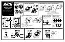
There are six status indicators (lights) on the front panel of the Back-UPS (On Line, On Battery,
Overload, Replace Battery, TX/RX, and ACT/LNK).
On Line (green) - is lit whenever AC utility power is
powering the outlets.
On Battery (yellow) - is lit whenever the battery of the
Back-UPS is supplying power to the equipment connected to
the outlets.
Four Beeps Every 30 Seconds - this alarm is
sounded whenever the Back-UPS is running On
Battery. Consider saving work-in-progress.
Overload (red) - is lit whenever power demand has
exceeded the capacity of the Back-UPS.
Continuous Tone - this alarm is sounded
whenever the Back-UPS outlets are overloaded.
Replace Battery (red) - is lit whenever the battery is
near the end of its useful life, or if the battery is not
connected (see above). A battery that is near the end of its
useful life has insufficient run-time and should be replaced.
Chirps for 1 Minute Every 5 Hours - this
alarm is sounded whenever the battery has failed
the automatic diagnostic test.
Continuous Beeping - this alarm is sounded
whenever a low battery condition is reached.
Battery run-time is very low. Promptly save any
work-in-progress and exit all open applications.
Shutdown the operating system, computer, and the
Back-UPS.
STATUS INDICATORS AND ALARMS
Back-UPS
H
S
5
00
Replace
Battery
OverloadOn Battery
On-Line
ACT/LNK
TX/RX
w
w
w
.apc.com
®
TX/RX (green) - is lit whenever the Back-UPS is
sending or receiving data over the network.
ACT/LNK (green) - is lit whenever the Back-UPS is
connected to equipment and is ready and waiting to send
or receive data.
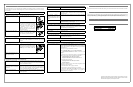
TRANSFER VOLTAGE/SENSITIVITY ADJUSTMENT (Optional)
Circuit Breaker - the rocker-type circuit breaker switch
located on the bottom panel of the Back-UPS will trip if an
overload condition forces the Back-UPS to disconnect
itself from AC utility power. If the switch trips, disconnect
non-essential equipment. Reset the circuit breaker by
pushing it to the ON position.
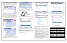
Follow the
on-screen
instructions.
INSTALL AND SETUP SOFTWARE
In situations where the Back-UPS or connected equipment appears too sensitive to input voltage, it may be
necessary to adjust the transfer voltage. This is a simple task requiring use of the front panel pushbutton. It can
also be accomplished using the Configuration Page Screen in the supplied software (see Install and Setup
Software). To adjust the transfer voltage, proceed as follows:
1. Plug the unit into an AC utility power source; the Back-UPS will go into Standby Mode (no indicators lit).
2. Press the front panel pushbutton fully inward for 10 seconds. All indicators on the Back-UPS will flash to
acknowledge going into Programming Mode.
3. The Back-UPS will then indicate its current Sensitivity Setting, as shown in the following table.
4. To select the Low Sensitivity setting, press the pushbutton until the yellow indicator is flashing.
5. To select the Medium Sensitivity setting, press the pushbutton until the yellow and red indicators are
flashing.
6. To select the High Sensitivity setting, press the pushbutton until yellow and both red indicators are flashing.
7. To exit without changing the Sensitivity Setting, press the pushbutton until the green indicator is flashing.
8. Once in Programming Mode, if the pushbutton is not pressed within 5 seconds, the Back-UPS will exit
Programming Mode; all indicators will extinguish.
Indicators
Flashing
Sensitivity
Setting
Input Voltage
Range (for
utility
operation)
Use When
1
(yellow)
Low 160 - 278 Vac Input voltage is extremely low or high. Not
recommended for computer loads.
2
(yellow, and red)
Medium
(factory default)
180 - 266 Vac Back-UPS frequently goes On Battery
(recommended).
3
(yellow, red, and red)
High 196 - 256 Vac Connected equipment is sensitive to voltage
fluctuations.
5. The software will display the Choose Destination Location Screen (Figure
4). Select Browse to find a location, click Next to accept the system default
location, the system will then display the Setup Status Screen (Figure 5).
Click on Cancel to stop the installation.
Figure 4. Choose Destination Location Screen
Figure 5. Setup Status Screen
6. The software then displays the InstallShield Wizard Complete Screen (Figure 6). Select
Finish to quit the installation program
..
Figure 6. InstallShield Wizard Complete Screen
7. To launch the program, go to the Start menu, select APC, then select APC Back-UPS HS
(Figure 7). Continued on the next page -
Figure 7. APC Software Startup Menu Selections