


14 MX28B
cable(s) must also carry the full load current during battery operation. If assistance is
required to determine the necessary cables for the application, contact your sales
representative or Advance Power, Inc.
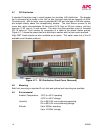
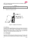
5.3.3 Connecting the Cables
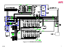
The battery cable connections are located at the top rear of the unit as shown in Figure
4.6-1. The battery positive (return bus) and battery negative (-48V bus) buses each provide
two sets of threaded 3/8”-16 holes on one-inch centers for connecting two-hole battery
cable lugs. Connect the battery cables as applicable using 3/8”-16 bolts (not provided) and
tighten them with a torque wrench to 200 in-lbs.
***** CAUTION *****
Make certain that the battery polarity is correct when making connections to the
Model MX28B dc power plant. Incorrect connection could cause severe equipment
damage.
5.4 DC SYSTEM GROUNDING
THE POSITIVE BATTERY CONNECTION (RETURN BUS) FOR THE POWER PLANT
MUST BE CONNECTED TO THE MASTER STATION GROUND. THE LEFT END OF
THE RETURN BUS PROVIDES A PAIR OF THREADED 3/8”-16 HOLES ON 1-INCH
CENTERS FOR CONNECTION OF A TWO-HOLE LUGGED CABLE TO THE MASTER
STATION GROUND. DETAILS FOR THIS CONNECTION SHOULD BE PROVIDED IN
THE SITE ELECTRICAL GROUNDING PLAN.
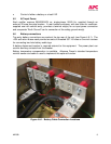
5.5 Rectifier Installation
The Advance Power, Inc. Model MRF28H54BV rectifiers are shipped in separate
containers. Follow the procedure below to install a rectifier.
1) Remove the rectifier from its shipping container.
2) Remove the rectifier retaining screw from the shelf position where the rectifier is to
be installed.
3) Slide the rectifier into the shelf between the guides until it is fully seated.
4) Fasten the rectifier in place with the rectifier retaining screw.
Since all adjustments are made from the system control unit, no rectifier adjustments are
necessary.
5.6 Alarm Connections
The alarm connections for all rectifiers, breakers, and fuses are factory pre-wired. The
MX28B dc power plant, however, permits the user to program the system alarms in various
ways.
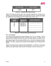
5.6.1 External Alarm Inputs
Four external alarm inputs with assignable priority levels are available. These alarm inputs
respond to external dry contact closures between normally open (NO) and common (C) or
contact openings between normally closed (NC) and C (see Table 5.6-1).