


22 MX28B
6.3 Alarm Output Relays
There are eight alarm output relays designated Relay 1 through Relay 6, Minor, and Major,
respectively. Various system parameters may be programmed to activate any of these
alarm relays when set thresholds are exceeded or specific conditions occur. The first six
relays can also be assigned a priority and routed or “mapped” to other output alarm relays.
Available assignments are “Ignore”, “Major”, “Minor”, and “Relay 1” ··· “Relay 6”. Screens
for making these assignments are located at [SYSTEM/OUT-RLY/RLY-MAP]. This feature
makes it possible for a single alarm condition to activate multiple alarm output relays
including the Minor or Major alarm relay. A user defined name or “alias” may also be
assigned to each of the eight output relay alarms. Screens for making these assignments
are located at [SYSTEM/OUT-RLY/ALIAS]. For information on making wiring connections
to the alarm output relays refer to Section 5.6.2.
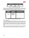
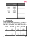
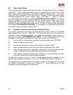
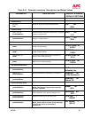
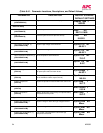
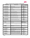
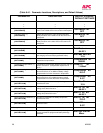
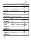
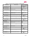
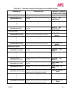
6.4 Parameter Locations, Descriptions, and Default Values
The location, description, and factory programmed default value for each of the MX28B
system parameters is found in Table 6.4.1. The table also shows all of the status and
information screens with typical displays. The location of a parameter screen is shown in
brackets, for example: [SYSTEM/IN-RLY/RLY-MAP]. To find the parameters that can be
accessed in this category, starting from the main menu screen, do the following:
1) Use the right or left arrow keys to position the cycling cursor below “SYSTEM”.
2) Press the down arrow key once.
3) Use the right arrow key to position the cycling cursor below “IN-RLY”.
4) Press the down arrow key once; the cursor will be cycling below “RLY-MAP”.
5) Press the down arrow key (repeatedly if necessary) until the desired parameter
screen is displayed (there are eight parameter screens in this category).
6) After making any desired changes (refer to Section 6.1 for the procedure), to return
to the main menu press the up arrow key repeatedly.
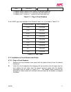
If a parameter requires a level 1 or level 2 security access to permit changes to it, the
security level will be found in braces, i.e. {2}, in the “PARAMETER” column of Table 6.4.1.
The complete menu structure shown in the order in which it is accessed from the control
unit display is presented in outline form in Figure 6.4-1. Each indentation to the right
represents a menu level below the indicated title.