


Operation and Features
SPD’s do not require a great deal of operator intervention after installation.
NOTE: The PM Series has a green LED for each phase which extinguishes when the module is no longer providing protec-
tion (fault condition).
All of the PM Series of SPDs contain a diagnostic circuit which monitors the suppressor status continuously and automati-
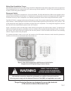
cally. If a fault condition were to occur, the built-in front panel audible alarm will sound and a red “Service” LED will light,
indicating that the unit is in need of service by a qualified technician.
The audible alarm can be silenced by pressing the “Mute Alarm” button on the touchpad, until a qualified electrician or
service person is available to service the unit. The red “Service” LED will continue to be illuminated even though the audible
alarm has been silenced. This will continue until the fault condition has been cleared.
Each of the internal surge protection modules have a green LED that lights to signify that the module is on-line and function-
ing properly (the N-G module does not have an LED). In addition to module LED’s, the front panel also displays the status
of each internal module by use of diagnostically controlled green LED’s. This technique ensures that a false indication does
not occur if an LED were to burn out. A true/hard fault condition can be confirmed by having an audible alarm with the red
“Service” LED lit, as well as any module LED and front panel status LED extinguished. By utilizing all of these built in
diagnostic features, an operator can more easily determine if a hard fault exists or if a status LED is faulty. If power is applied
the SPD and one or more of the module LED’s are extinguished and any diagnostic LED on the font panel concurs with any
module LED, then the faulted module may need to be replace. Use the troubleshooting section of the manual to locate and
repair the fault.
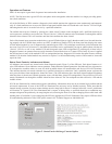
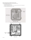
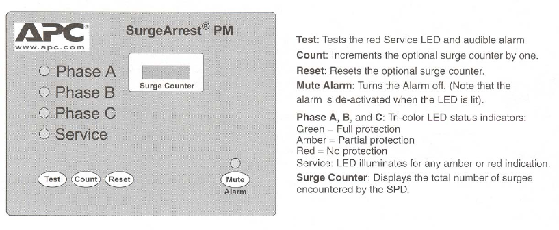
Status Panel Controls, Indicators and Alarms
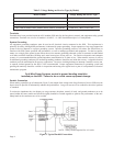
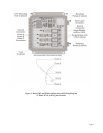
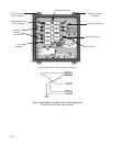
All indicators and controls are located on the front diagnostic panel (Figure 5) of the SPD unit. Each phase features a tri-
color LED indicator. Green indicates correct operation. Amber indicates reduced protection. Red indicates loss of protection.
If an inoperative condition where to occur, the built-in audible alarm will sound and the red Service LED will illuminate.
This indicates that the unit needs evaluation by a qualified electrician or technician. Until a qualified person evaluates the
unit, press the Mute Alarm touchpad to silence the alarm. (The LED indicator above the Mute Alarm touchpad illuminates
when the alarm is deactivated. Normal operation occurs with the Mute Alarm LED extinguished.) The red Service LED will
remain illuminated even though the Audible Alarm has been silenced. The Test touchpad tests the red Service LED and the
Audible Alarm.
If LEDs are illuminated in a manner that suggests contradictory information, there may be an internal logic problem and the
unit needs replacement. If none of the LEDs are illuminated, the unit may not be installed correctly. Please note that the
internal storage capacitor for surge counter backup must be energized for about 15 minutes before the “count” push button
will function. If a green LED is not illuminated and is suspect of being faulty, a qualified electrician or technician may
attempt to diagnose the problem by de-energizing the unit, removing the front cover and exchanging ribbon cable leads with
another phase (if available). Upon reenergizing the SPD, the appropriate LED will illuminate if the suspect LED has failed.
If troubleshooting indicates a failed LED, please contact APC Technical Support at: 800-800-4APC.
Page 9
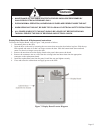
Figure 5. Status Panel with Surge Counter Option