


Page 17
4.6 Transformer
The PowerCell’s transformer is an electrical component which “steps up” the
output voltage of the inverter to the normal utility line voltage (115 Vac). In
addition, it serves to isolate the PowerCell from equipment failures.
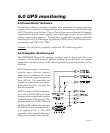
4.7 Monitoring and control electronics
This block is the “brain” of the PowerCell. The monitoring and control circuitry
detects utility failures such as blackouts, sags and brownouts; synchronizes the
inverter’s output frequency and phase to that of the utility; detects low battery
voltage conditions; directs the load transfer switch; and governs all user controls,
indicators and computer interface functions.
4.8 Operation during a utility failure
In anticipation of a utility failure such as a blackout, sag or brownout, the
PowerCell continuously monitors the utility voltage and readies the inverter for
“synchronous” transfer. This means the inverter’s phase and frequency is
adjusted to exactly match the phase and frequency of the utility. If the utility
voltage falls outside acceptable limits, the PowerCell rapidly transfers your
equipment to power derived from the UPS’s battery via the inverter and trans-
former described earlier. This transfer typically takes place within 3 millisec-
onds. Once operating in this mode, the PowerCell will emit a beep once every five
seconds to remind you that the continuation of power is limited in duration. If
the utility power is not restored to normal, the PowerCell will eventually sound
a loud tone to alert you that less than two minutes remain before the UPS shuts
down and ceases to power your equipment. This is called a low battery condition
which means that the PowerCell’s usable battery capacity is nearly spent. The
PowerCell will automatically shut down if it is not turned off during the low
battery alarm.
If the PowerCell detects the return of normal utility voltages at any time during
operation using its alternate power source, the inverter voltage will be smoothly
re-synchronized to match the phase and frequency of the utility. Once synchro-
nized, the load transfer switch will re-transfer your equipment to power supplied
by the utility. After an extended utility outage, the battery charger resupplies the
battery with energy at a pace which is consistent with maximizing the service life
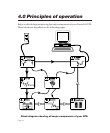
4.0 Principles of operation