


Contents
iv Reference Manual ReadyBoard 700
LCD Interface (J9)........................................................................................................................ 47
LVDS Interface (J7) ..................................................................................................................... 48
Miscellaneous................................................................................................................................... 49
Utility Interface (J18).................................................................................................................... 49
Reset Switch (SW1)..................................................................................................................... 49
Keyboard/Mouse Interface (J16) ................................................................................................. 49
Infrared (IrDA) Port (J17)............................................................................................................. 50
Real Time Clock (RTC)................................................................................................................ 50
Oops! Jumper (BIOS Recovery).................................................................................................. 50
User GPIO Signals (J2) ............................................................................................................... 51
Temperature Monitoring............................................................................................................... 51
Serial Console.............................................................................................................................. 51
Watchdog Timer........................................................................................................................... 52
Power Interfaces (J4, J6) ................................................................................................................. 53
Power In Interface (J4)................................................................................................................. 53
Power-On Interface (J6)............................................................................................................... 53
Chapter 4 BIOS Setup................................................................................................................... 55
Introduction....................................................................................................................................... 55
Accessing BIOS Setup (VGA Display)......................................................................................... 55
Accessing BIOS Setup (Serial Console)...................................................................................... 56
BIOS Menus..................................................................................................................................... 57
BIOS Setup Opening Screen.......................................................................................................57
BIOS Configuration Screen.......................................................................................................... 58
Splash Screen Customization.......................................................................................................... 70
Splash Screen Image Requirements........................................................................................... 70
Converting the Splash Screen File .............................................................................................. 70
Appendix A Technical Support ....................................................................................................... 73
Appendix B LAN Boot Option.......................................................................................................... 75
Introduction....................................................................................................................................... 75
PXE Boot Agent BIOS Setup ........................................................................................................... 76
Accessing PXE Boot Agent BIOS Setup ..................................................................................... 76
PXE Boot Agent Setup Screen .................................................................................................... 77
Index ....................................................................................................................................... 79
List of Figures
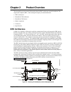
Figure 2-1. Stacking PC/104 Modules with the ReadyBoard 700..................................................... 5
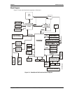
Figure 2-2. ReadyBoard 700 Functional Block Diagram .................................................................. 9
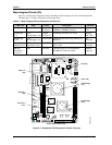
Figure 2-3. ReadyBoard 700 Component Location (Top view) ...................................................... 10
Figure 2-4. Connector Locations (Top view)................................................................................... 12
Figure 2-5. Connector and Component Locations (Bottom view)................................................... 13
Figure 2-6. Jumper, Switch, and LED Locations (Top view)........................................................... 15
Figure 2-7. ReadyBoard 700 Dimensions (Top view)..................................................................... 17
Figure 2-8. ReadyBoard 700 Panel Dimensions (Side view).......................................................... 18
Figure 3-1. RS485 Serial Port Implementation ............................................................................... 39
Figure 3-2. Oops! Jumper Connection............................................................................................51
Figure 3-3. Hot Cable Jumper......................................................................................................... 52
Figure 4-1. Opening BIOS Screen.................................................................................................. 57
Figure 4-2. Modifying Setup Parameters Screen............................................................................ 58