


Chapter 4 BIOS Setup
66 Reference Manual ReadyBoard 700
♦ Panel Type – [640 x 480 x 18 TFT]
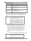
Refer to Table 4-3 for the list of supported resolutions and flat panel types. Some LCD panels
may require video BIOS modifications. It you think this is the case, or would like help in
setting up your LCD panel, contact Ampro for assistance with the LCD panel adaptation.
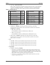
Table 4-3. LCD Panel Type List
# LCD Resolution
LCD
Type
# LCD Resolution
LCD
Type
1
640 x 480 x 18 (bit) TFT
9 640 x 480 x 18 (bit) TFT*
2 800 x 600 x 18 (bit) TFT* 10 800 x 600 x 18 (bit) TFT
3 1024 x 768 x 18 (bit) TFTx2 11 1024 x 768 x 18 (bit) TFT
4 1280 x 1024 x 18 (bit) TFTx2 12 1280 x 1024 x 18 (bit) TFT
5 640 x 480 x 16 (bit) DSTN 13 1400 x 1050 x 18 (bit) TFTx2
6 800 x 600 x 16 (bit) DSTN* 14 800 x 600 x 16 (bit) DSTN*
7 1600 x 1200 x 18 (bit) TFTx2 15 1024 x 768 x 16 (bit) DSTN
8 1024 x 768 x 18 (bit) TFT* 16 1280 x 1024 x 16 (bit) DSTN
• On-Board Audio Legacy
♦ SoundBlaster – [Disabled], [220-22Fh], [240-24Fh], [260-26Fh], or [280-28Fh]
This field indicates the base address of the on-board Audio controller used to emulate the
SoundBlaster, or is disabled.
• IRQ – [5], [7], [9], or [10]
If the SoundBlaster emulation is [Disabled], then no IRQ is used.
• DMA – [3], [2], [1], or [0]
If the SoundBlaster emulation is [Disabled], then no DMA channel is used.
♦ MPU 401 Midi – [Disabled], [300-303h], [310-313h], [320-323h], or [330-333h]
This field indicates the base address of the on-board Audio controller used to emulate
MPU-401 Midi, or is disabled.
• PCI
♦ INTA IRQ – [none], [1], [3], [4], [5], [6], [7], [9], [10], [11], [12], [14], or [15]
♦ INTB IRQ – [none], [1], [3], [4], [5], [6], [7], [9], [10], [11], [12], [14], or [15]
♦ INTC IRQ – [none], [1], [3], [4], [5], [6], [7], [9], [10], [11], [12], [14], or [15]
♦ INTD IRQ – [none], [1], [3], [4], [5], [6], [7], [9], [10], [11], [12], [14], or [15]
• Plug and Play
♦ PnP BIOS – [Disabled] or [Enabled]
• If this field is set to [Enabled], the BIOS uses Plug and Play adapter initialization and
assigns the resources, such as I/O addresses, IRQs, and DMA channels to Plug and Play
compatible devices. The resources assigned by the BIOS are based on the settings of the
IRQ and DMA channel assignments listed in the following fields.
• If this field is set to [Disabled], the IRQs and DMA channels listed below can not be
assigned to Plug and Play devices.