


Chapter 3 Hardware
ReadyBoard 700 Reference Manual 45
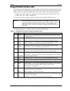
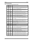
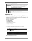
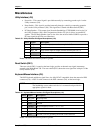
Table 3-18. Ethernet Port 2 Pin/Signal Descriptions (J11)
Pin # GND Digital Ground
1TX2+
3TX2-
Analog Twisted Pair Ethernet Transmit Differential Pair. These pins transmit
the serial bit stream for transmission on the Unshielded Twisted Pair Cable
(UTP). These signals interface directly with an isolation transformer.
4RX2+
6RX2-
Analog Twisted Pair Ethernet Receive Differential Pair. These pins receive
the serial bit stream from the isolation transformer.
9 ACT Link/Activity signal indicates a Link is established or Activity is occurring
11 SPEED Speed signal for 10BaseT or 100BaseT transfer rate
2, 7, 8 NC Not connected
5, 13, 14 GND
Grounded (goes to ground through 0.1µ capacitor)
10, 12 +3VSB +3V for plus side of LEDs. See Table 2-7.
Notes: The shaded area denotes power or ground.
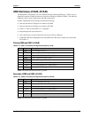
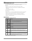
Audio Interface (J19)
The audio solution on the ReadyBoard 700 is provided by the Southbridge (VT82C686B) and the ion
board Audio CODEC (VT1612A). These two chips communicate through a digital interface, defined
by and compliant with AC’97 Rev 2.2. Input or output signals for the audio interface go through the 16-
pin connector (J19) to an external cable and/or board, which has the respective audio connections. The
PC-Beep Speaker signal from the Southbridge is also fed to the on board Audio CODEC to provide a
PC-beep signal for the stereo line out connections.
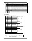
Audio CODEC (VT1612A) features
• AC’97 Rev 2.2 compliant
• 18-bit full duplex performance
• Variable sampling rate at 1Hz resolution
• Stereo (Left and Right) Line In
• Stereo (Left and Right) Line Out
• Microphone (mono) in
• PC-Beep speaker signal through the Stereo (Left and Right) Line Out connections
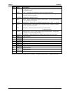
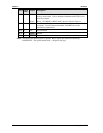
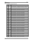
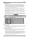
Table 3-19. Audio Interface Pin/Signal Descriptions (J19)
Pin # Signal Description
1, 3 NC Not Connected
2, 4, 7, 8, 11,
12, 13, 14, 16
GND_AUD Audio ground
5 LINEOUTL Line Out signal left channel
6 LINEOUTR Line Out signal right channel
9 LINE_IN_L Line in signal left channel
10 LINE_IN_R Line in signal right channel
15 MICIN Microphone signal in
Notes: The shaded area denotes power or ground.