


Chapter 3 Hardware
ReadyBoard 700 Reference Manual 41
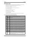
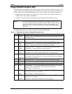
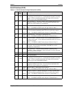
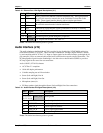
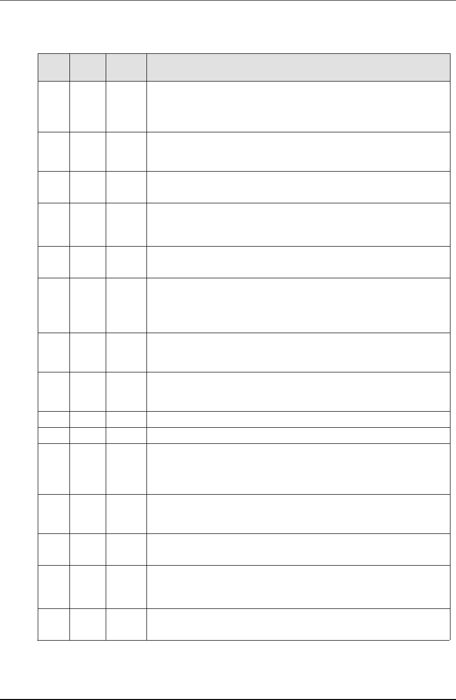
Serial B Interface (J3A/B)
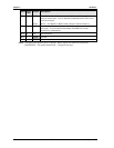
Table 3-14. Serial B Interface Pin/Signal Descriptions (J3A/B)
Pin # Pin #
DB9
Signal Description
A1 1
(COM3)
DCD3*
Data Carrier Detect 3 – Indicates external serial communications device
is detecting a carrier signal (i.e., a communication channel is currently
open). In direct connect environments, this input will be driven by
DTR3 as part of the DTR/DSR handshake.
A2 6 DSR3* Data Set Ready 3 – Indicates external serial communications device is
powered, initialized, and ready. Used as hardware handshake with
DTR3 for overall readiness to communicate.
A3 2 RXD3
RX3-
Receive Data 3 – Serial port 3 receive data in.
RX3- – If in RS485 or RS422 mode, this pin is Receive Data 3 -.
A4 7 RTS3*
TX3+
Request To Send 3 – Indicates Serial port 3 is ready to transmit data.
Used as hardware handshake with CTS3 for low level flow control.
TX3+ – If in RS485 or RS422 mode, this pin is Transmit Data 3 +.
A5 3 TXD3
TX3-
Transmit Data 3 – Serial port 3 transmit data out.
TX3- – If in RS485 or RS422 mode, this pin is Transmit Data 3 -.
A6 8 CTS3*
RX3+
Clear To Send 3 – Indicates external serial communications device is
ready to receive data. Used as hardware handshake with RTS3 for low
level flow control.
RX3+ – If in RS485 or RS422 mode, this pin is Receive Data 3 +.
A7 4 DTR3*
Data Terminal Ready 3 – iIndicates Serial port 3 is powered, initialized,
and ready. Used as hardware handshake with DSR3 for overall
readiness to communicate.
A8 9 RI3*
Ring Indicator 3 – Indicates external modem is detecting a ring
condition. Used by software to initiate operations to answer and open
the communications channel.
A9 5 GND Ground
A10 NC NC Not connected/Key
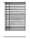
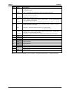
B11 1
(COM4)
DCD4* Data Carrier Detect 4 – Indicates external serial communications device
is detecting a carrier signal (i.e., a communication channel is currently
open). In direct connect environments, this input will be driven by
DTR4 as part of the DTR/DSR handshake.
B12 6 DSR4* Data Set Ready 4 – Indicates external serial communications device is
powered, initialized, and ready. Used as hardware handshake with
DTR4 for overall readiness to communicate.
B13 2 RXD4
RX4-
Receive Data 4 – Serial port 4 receive data in.
RX4- – If in RS485 or RS422 mode, this pin is Receive Data 4 -.
B14 7 RTS4*
TX4+
Request To Send 4 – Indicates Serial port 4 is ready to transmit data.
Used as hardware handshake with CTS4 for low level flow control.
TX4+ – If in RS485 or RS422 mode, this pin is Transmit Data 4 +.
B15 3 TXD4
TX4-
Transmit Data 4 – Serial port 4 transmit data out.
TX4- – If in RS485 or RS422 mode, this pin is Transmit Data 4 -.