


Advanced Programming
21
ALD-H48 Lighting Controller
Port Mapping
This module uses multiple virtual devices in order distinguish events for one keypad from another.
Channel Assignment and Feedback
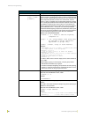
While channel 251 is ON, the AMX system and the H48 are communicating.
While channel 252 is ON, the Duet module has been initialized with the latest H48 data.
Each keypad added to the keypad component list (see KEYPADADD-<index>,<addr> command)
is controlled by turning a channel ON/OFF or by generating a button PUSH/RELEASE similar to a
Netlinx native device. The virtual device you assign in your project will be used to accomplish this
as follows: the virtual port number of your virtual device's D:P:S will represent the keypad number
(1..24) and the channel will represent the keypad button (1..24). Most keypads, at this time, have a
maximum of 10 LEDs, so LEDs 11 through 24 will not have a visual notification in this case, but
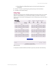
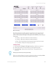
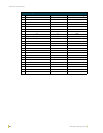
they will have a virtual notification. The table below shows the mapping of channels to keypad
buttons/LEDs. Ports 1 through 24 and channels 1 through 24 on each port are used and cannot be
changed. To indicate a flashing LED, channels 101..124 are used.
Example of use: Suppose you assign a virtual device number 41001:1:0 in your application code.
All commands to and from the Duet code will use this virtual device as usual. If so desired,
additional keypad control can be accomplished by turning ON/OFF channels or by doing a PUSH/
RELEASE. So, suppose you turn ON channel 4 on virtual device 41001:1:0, then this will turn ON
the LED on keypad 1 button 4. If you want to turn OFF the LED on keypad 5 button 7, then all you
have to do is turn OFF channel 7 on virtual device 41001:5:0. As you can see, the port number is
used to tell what keypad to control and the channel is used to tell what button to affect. Similarly, if
someone turns ON the LED on keypad 5 button 7, then channel 7 on virtual device 41001:5:0 will
turn ON. The keypad LEDs can be turned OFF or ON, and the keypad buttons can be PUSHed or
RELEASEd in this way. You may also FLASH a specific keypad LED. In order to flash you must
turn ON the matching channel+100. In other words, if you would like to flash keypad LED number
7 then turn ON channel 107. To stop flashing you must turn off the channel described in the below
table, so for the above example, you would turn OFF channel 7. To transition from FLASH to ON
in the above example, you must first turn OFF channel 7, and then turn channel 7 back ON.
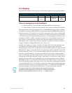
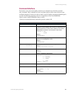
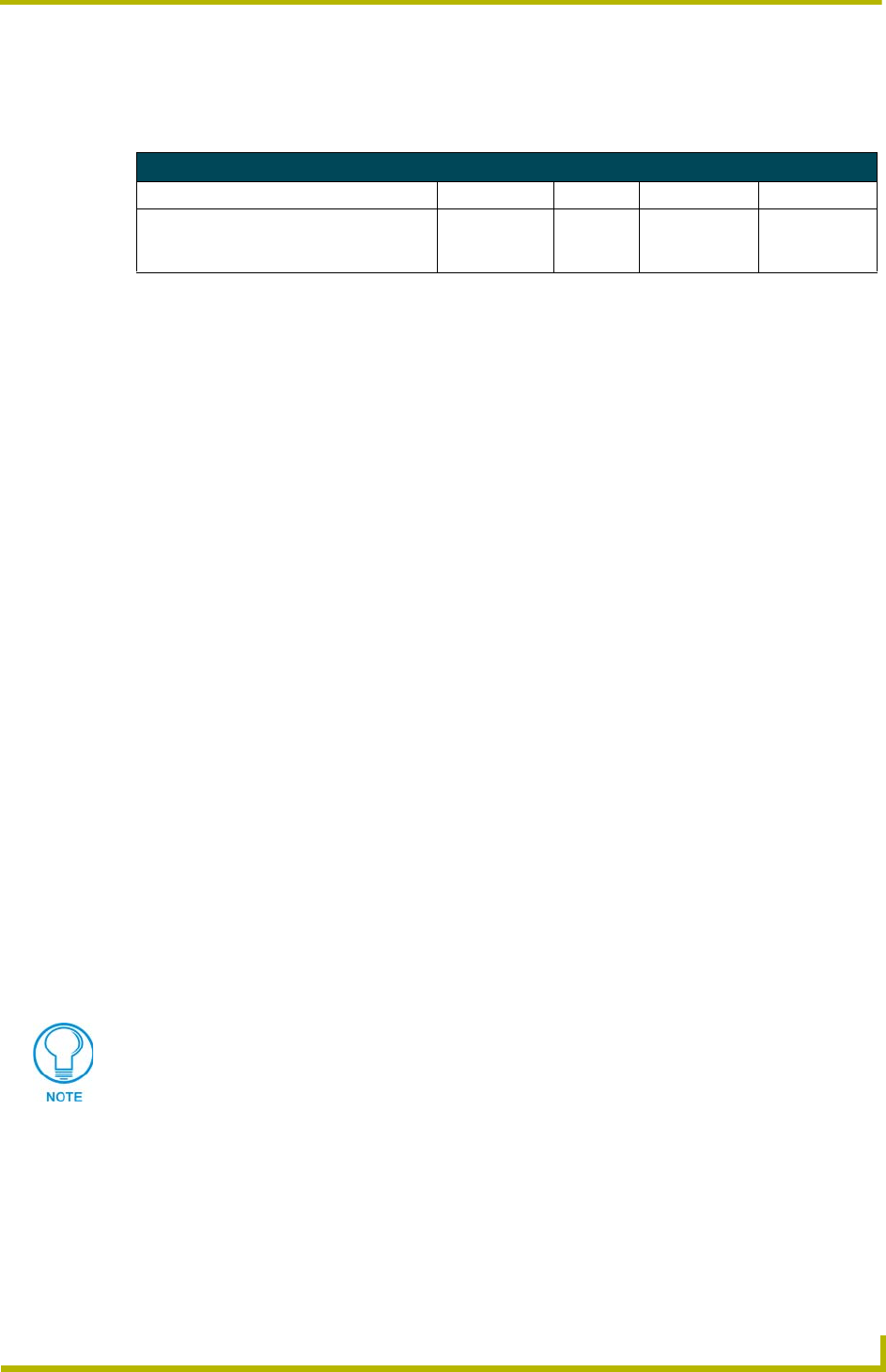
Port Mapping
Virtual Device Channels Levels Control Feedback
41001:n:0 - {keypad n=1..24} 1..24
&
101..124
none PUSH
RELEASE
ON
OFF
FLASH
The keypad number is the number assigned to each keypad by making the
appropriate dipswitch assignments on the back of it. If looking at the protocol
document, the last address parameter (i.e. [1:5:x] x = keypad number)