


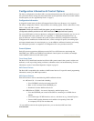


Overview & General Specifications
9
Precis SD Instruction Manual
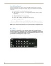
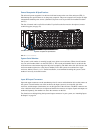
Rear View
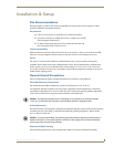
The enclosure’s appearance, as viewed from the rear, (FIG. 2) will vary depending on the configuration.
Rear View Components
CPU/Control hardware
Power receptacle and specifications
Serial number
Input/output connectors
The following sections briefly introduce the hardware on the rear of an enclosure.
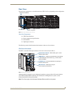
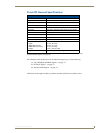
CPU/Control Hardware
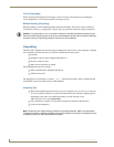
The CPU is to the left of the input connectors on the rear of the enclosure (FIG. 3).
Although primarily designed as a pre-engineered, standalone system, the Precis SD can be linked to
other AMX AutoPatch Matrix Switchers. For information on linking between systems, see the
instruction manual for the specific product.
Note: The Comm light on the front panel indicates Ethernet traffic on the system.
FIG. 2 Precis SD 12x8 enclosure rear view
FIG. 3 CPU/Control hardware
Power receptacle
Input connectors
Output connectors
CPU/Control hardware
Serial number
System Status indicator – Blinks either green or red to
indicate system status.
REMOTE Port – XNNet communication link port for linking
to AMX AutoPatch control devices (e.g., remote control
panels and SBCs).
ENC LINK Port – Ethernet (RJ-45) port.
Can be used to link enclosures.
CONTROL port – Serial port (RS-232) for attaching an
external control device.