


Overview & General Specifications
10
Precis SD Instruction Manual
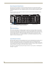
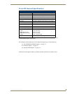
Power Receptacle & Specifications
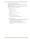
The universal power receptacle is in the lower left hand corner on the rear of the enclosure (FIG. 4).
Maximum power specifications are on the power receptacle. The power receptacle will accept all major
international standard power sources. (Standard US power cords are provided for installations within
the US.)
The fuse is internal and is not field serviceable. If you believe the fuse needs to be replaced, contact
technical support (see page 32).
System Serial Number
The system’s serial number is normally located in two places on an enclosure. When viewed from the
rear, one serial number label is on the CPU (FIG. 4). The second serial number label is on the left side
of the enclosure at the bottom edge (near the power receptacle). The label on the side will also have the
enclosure number (referred to as the chassis number). Precis SD systems are contained in a single
enclosure, labeled “Chassis 1 of 1.” Before installation, we recommend recording the system’s serial
number in an easily accessible location.
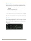
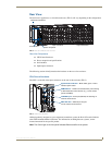
Input & Output Connectors
Input and output connectors are the attachment points for source and destination devices that connect to
the system. Viewed from the rear of the enclosure, the inputs (sources) are on the left side of the
enclosure, and the outputs (destinations) are on the right side of the enclosure. The BNC connectors are
color coded; the white connectors are inputs and the black connectors are outputs. Inputs and outputs are
numbered separately; the numbers are above the connector on the left.
For directions on cabling/wiring the input and output connectors in your system, see “Attaching Inputs
& Outputs” on page 24.
FIG. 4 Enclosure hardware
Input connectors
Output connectors
Power receptacle & specifications
Serial number labels