


Wiring and Device Connections
11
TPI-PRO Total Presentation Interface - Pro Edition
Wiring and Device Connections
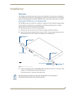
Overview
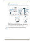
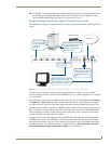
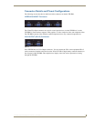
Most device connections are made via the ports on the rear panel of the TPI-PRO (FIG. 6).
For detailed descriptions of the rear panel connectors, refer to the Connector Details and Pinout
Configurations section on page 17.
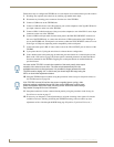
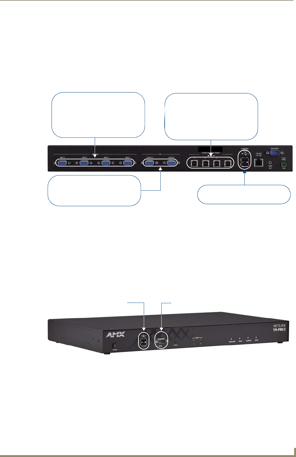
The only connectors on the front panel are two USB (Type A) ports, which allow the TPI-PRO to
connect an input device like a USB touch monitor, mouse, or keyboard, and a RS-232 SERIAL
(Configuration) port (
FIG. 7).
See the Programming section on page 75 for a detailed description of the front panel RS-232 SERIAL
port and a listing of supported NetLinx Send_Commands
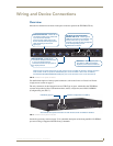
FIG. 6 TPI-PRO-4 - rear panel connectors
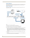
FIG. 7 TPI-PRO-4 - front panel connectors
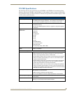
VGA OUTPUTS - These HD-15
connectors distribute TPI-PRO video
to up to two display devices.
Connect to the HD-15 Input ports on
the display devices.
SOURCE TOUCH/KEYBOARD/
MOUSE USB Ports - These Type-B
USB ports provide touch, keyboard, and
mouse control from up to four PCs.
Note that the rear panel connectors on both versions of the TPI-PRO are identical, with the exception
of the number of HD-15 inputs for VIDEO/VGA (four on the TPI-PRO-4, two on the TPI-PRO-2),
and SOURCE KEYBOARD/MOUSE USB ports (four on the TPI-PRO-4, two on the TPI-PRO-2).
Connect to source PC that corresponds
to the corresponding source
VIDEO/VGA connector.
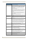
VIDEO/VGA INPUTS - These HD-15
connectors accept source video from
up to four Source devices.
Connect to the output ports on the
Source devices with the appropriate
cable according to the source
signal type.
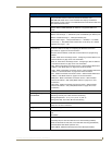
USB Ports - These Type-A ports
are used for USB Touch Monitor,
keyboard, and mouse connections.
Note that the front panel connectors on both versions of the TPI-PRO are identical.
USB Ports (Type A) SERIAL Configuration Port (DB-9)