


3
4
4 Amp Microstep Driver MDM40001
6 Amp Microstep Driver MDM60001 (This Manual)
10 Amp Microstep Driver MDM10001
40VDC Power Supply PSA40V4A (For MDM40001)
40VDC Power Supply PSA40V8A-2 (For MDM40001)
Includes +5Vdc Supply
65VDC Power Supply PSA65V5A (For MDM60001)
65VDC Power Supply PSA65V5A-2 (For MDM60001)
Includes +5Vdc Supply
80VDC Power Supply PSA80V4A (For MDM10001)
Shielded Motor Cable AA129010S
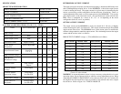
ORDERING INFORMATION FOR ANAHEIM AUTOMATION
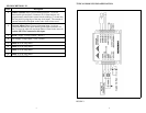
MICROSTEP DRIVERS AND ACCESSORIES PIN DESCRIPTIONS P1
MDM40001
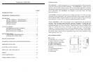
This is the model number for a Single Axis, 4 Amp Microstep Driver. The MDM40001
requires a dc power supply (up to 48 volts).
MDM60001
This is the model number for a Single Axis, 6 Amp Microstep Driver. MDM60001
requires a 65Vdc power supply (PSA65V5A-2) that Anaheim Automation provides,
purchased separately.
MDM10001
This is the model number for a Single Axis, 10 Amp Microstep Driver. The MDM10001
requires an 80Vdc power supply (PSA80V4A) that Anaheim Automation provides,
purchased separately.
PSA40V4A
This is an unregulated 40VDC, 4 Amp power supply.
PSA65V5A
This is an unregulated 65VDC, 5 Amp power supply.
PSA80V4A
This is an unregulated 80VDC, 4 Amp power supply.
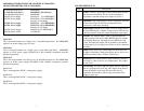
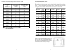
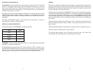
Pin# Description
1 Clock: A positive going edge on this isolated input advances
the motor one increment. The size of the increment is
dependent on the Microstep Select Inputs of Switch 1.
2 Direction: This isolated input is used to change the direction
of the motor. Physical direction also depends on the
connection of the motor windings.
3 Opto Supply (+5VDC): This input is used to supply current
to the Isolated Inputs. A higher voltage may be used, but care
should be taken to limit the current through the optocoupler.
4 On/Off: This isolated input is used to enable/disable the
output section of the driver. When HIGH (open) the outputs
are enabled. However, this input does not inhibit the step
clock. Therefore the outputs will be updated by the number
of clock pulses (if any) applied to the driver while it had been
disabled.
5 Reset: When LOW, this isolated input will reset the driver
(outputs will disable). When released, the driver will be at its
initial state (Phase 1&3 off, Phase 2&4 full on).
6 Fault Out: This OPEN DRAIN output indicates a fault has
occurred (ie. short circuit or over temperature). This output
is active low.
7 On F/S Out: This OPEN DRAIN output indicates when the
driver is positioned at a full step. This output can be used to
count the number of full steps the motor has moved,
regardless of the number of microsteps in between. This
output is active low.
Table 1 - CONNECTOR P1