


11
12
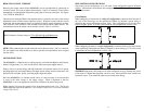
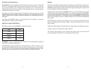
4 Lead Motors CONNECTING THE STEP MOTOR
Use the specified series motor current to determine the current adjustment resistor value.
Four Lead Motors are usually rated with their appropriate series current, as opposed to the
Phase Current which is the rating for 6 and 8 lead motors.
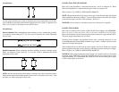
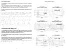
8 Lead Motors
Series Connection: When configuring the motor windings in series, multiply the per Phase
(or unipolar) current rating by 0.7. Use this result to determine the current adjustment
resistor value.
Parallel Connection: When configuring the motor windings in parallel, multiply the per
Phase (or unipolar) current rating by 1.4. Use this result to determine the current
adjustment resistor value.
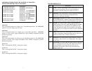
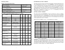
NOTE: After the current has been determined, according to the motor connections above,
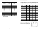
follow the procedure Determining Output Current above to find the current value. Then
use Table 3 to choose the proper resistor value.
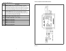
Phase 1&3 of the Step Motor is connected between pins 7 and 8 on connector P2. Phase
2&4 of the Step Motor is connected between pins 5 and 6 on connector P2.
Refer to Figure 1 for TYPICAL APPLICATION HOOK-UP
NOTE: The physical direction of the motor with respect to the direction input will depend
on the connection of the motor windings. To reverse the direction of the motor with respect
to the direction input, switch the wires on Phase 1 & Phase 3.
WARNING: Do not connect or disconnect motor wires while power is applied!
CONNECTING POWER
Pins 3 and 4 on connector P2 are used to connect the DC Power Supply to the MDM60001.
Wire size used to connect the power source to the driver should be at least 16 gauge.
Heavier wire should be used for longer distances between the power supply and the driver.
The power supply requirements are as follows:
Switching Power Supplies and regulated linears with overcurrent protection are not
recommended because of their inability to handle surge currents. Adding a capacitor to the
output will alleviate this problem.
When multiple drivers are run from one power supply, each driver should have separate
power and ground wires that connect directly to the output capacitor of the power supply.
Refer to Figure 1 for TYPICAL APPLICATION HOOK-UP.
WARNING: When using an unregulated power supply, care should be taken to ensure that
the output voltage DOES NOT exceed the maximum driver input voltage because of line
voltage fluctuations. It is recommended that a input line filter be used on the power supply
to limit voltage spikes to the driver.