


15
16
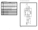
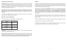
FULLSTEP OUTPUT SIGNAL TIMING
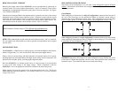
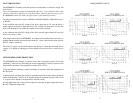
The MDM60001 has an active LOW open drain output at Connector P1, Pin 7 labeled ON The Direction and Microstep Resolution Select inputs are synchronized with the positive
F/S OUT. This output is TRUE (active low) for the duration of the full step. A full step going edge of the Step Clock input. When the Step Clock input goes high, the Direction
occurs when either Phase 1&3 or Phase 2&4 cross through zero (ie. full current in one and Microstep Select inputs are latched and further changes to the inputs are ignored until
winding and 0 current in the other winding). This full step position is a common position the next rising edge of the Step Clock input.
no matter what resolution is selected.
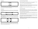
This output can be used to count the number of mechanical full steps the motor has traveled to the Direction and the Microstep Select inputs. If a change has occurred, the MDM60001
without having to count the number of microsteps in between. A controller that utilizes this will execute the change before taking the next step. Only AFTER the change has been
output can greatly reduce its position tracking overhead and thus substantially increase its executed will the step be taken. If no change has occurred the MDM60001 will simply take
throughput. the next step. This feature works as an automatic debounce for the Direction and Microstep
This high speed MOSFET output is non-isolated and has the ability to sustain the
maximum driver voltage at 25mA maximum. The minimum pulse width for the Clock input is 75 nS. The typical execution time for a
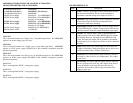
OPTICALLY ISOLATED INPUTS input is 100nS.
The following inputs to the MDM60001 are Optically Isolated. The Reset and Enable inputs are asynchronous to any input and can be changed at any time.
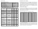
Item Pin #
Clock 1
Direction 2
On/Off 4
Reset 5
WARNING! If using a voltage other than +5VDC, the current through the optocoupler
must NOT exceed the maximum limit.
The Isolated inputs may be powered by a DC voltage other than +5 VDC. In doing so, care
should be taken to limit this current, an external resistor should be placed in series with the
input pins (1-2, 4-5). The value of the resistor should be calculated such that the input
current is approximately equal to the value listed in the Electrical Specifications.
After these signals are latched, the MDM60001 looks to see if any changes have occurred
Select inputs.
Direction or Microstep Select change is 100nS. The typical execution time for a Clock
The Reset requires a minimum pulse width of 500 nS.
The Fullstep output typically occurs 75nS after the positive edge of the Step Clock
(excluding changes to the Direction or the Microstep Select inputs).