


7
8
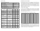
SPECIFICATIONS DETERMINING OUTPUT CURRENT
ABSOLUTE MAXIMUM RATINGS The output current for the motor used when microstepping is determined differently from
INPUT VOLTAGE +24 TO +75 VDC
OUTPUT CURRENT 6 AMPS PEAK
PLATE TEMPERATURE 70° C
STORAGE TEMPERATURE 40° TO +125° C
INPUT CURRENT (PINS 1, 2, 4, 5) 15 mA Max
ELECTRICAL SPECIFICATIONS (TA=25EEC, V+ = 75VDC)
ITEM TEST CONDITION MIN TYP MAX UNIT
S
Input Voltage 24 75 V
Phase Output Current RMS 1 4 A
Phase Output Current Peak 1.4 6 A
Quiescent Current Outputs Floating 13 mA
Active Power Iout=4 Amps RMS 9 W
Dissipation
Input Forward Current Input Pins 7 15 mA
1, 2 , 4, 5
Input Forward Voltage 1.4 1.7 V
Input Reverse 5 V
Breakdown Voltage
Output Current Fault, Fullstep 25 mA
Outputs
Collector-Emitter Fault Output 140 V
Voltage
Collector-Emitter Fault Output 0.2 V
Saturation Voltage Ics=25mA DC
Drain-Source Voltage Fullstep Output 100 V
Drain-Source on Fullstep Output 6.5 ohms
Resistance Ics=25mA DC
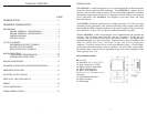
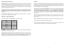
that of a halfstep/fullstep unipolar driver. In the MDM60001, a sine/cosine output current
is used in rotating the motor. The output current for a given motor is determined by the
motors current rating and the configuration for how the motor is hooked up. There is a
current adjustment resistor used to set the output current of the MDM60001. This sets the
peak output current of the sine/cosine waves. The specified motor current (which is the
RMS value) is multiplied by a factor of 0.7, 1.0, or 1.4 depending on the motor
configuration (half-coil, series, or parallel).
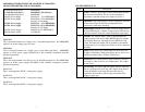
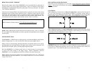
SETTING OUTPUT CURRENT
The output current on the MDM60001 is set by an external ±1%, 1/8 watt (or higher)
resistor between pins 2 and 3 of connector P2. This resistor determines the per Phase RMS
output current of the driver. The MDM60001 uses a 2mA current source to establish the
reference voltage needed to control the output current. The relationship between the output
current and the resistor value is as follows:
RMS OUTPUT CURRENT (Amps) = (.707)(0.002)(Resistor in Ohms)
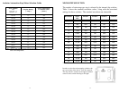
RMS Current Resistor Value RMS Current Resistor Value
1.0 698 2.5 1740
1.2 845 2.6 1820
1.4 988 2.7 1890
1.6 1110 2.9 2030
1.7 1180 3.0 2100
1.9 1330 3.2 2230
2.0 1400 3.3 2320
2.2 1540 3.4 2370
2.3 1600 3.8 2670
2.4 1670 4.0 2870
TABLE 3: RESISTOR VALUES WITH RESPECT TO OUTPUT CURRENT
Closest 1% value selected
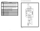
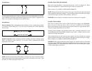
WARNING! A current adjustment resistor is always necessary to keep the drive in a safe
operating region. Do not operate the driver without a current adjustment resistor. When
connecting the CURRENT ADJUSTMENT resistor between Pins 3 and 2 of Connector P2
the length of the leads should be as short as possible to help minimize the noise coupled
into the driver . Refer to Figure 1 for TYPICAL HOOK-UP.