


UG-002 Evaluation Board User Guide
Rev. 0 | Page 10 of 12
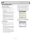
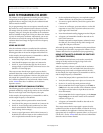
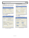
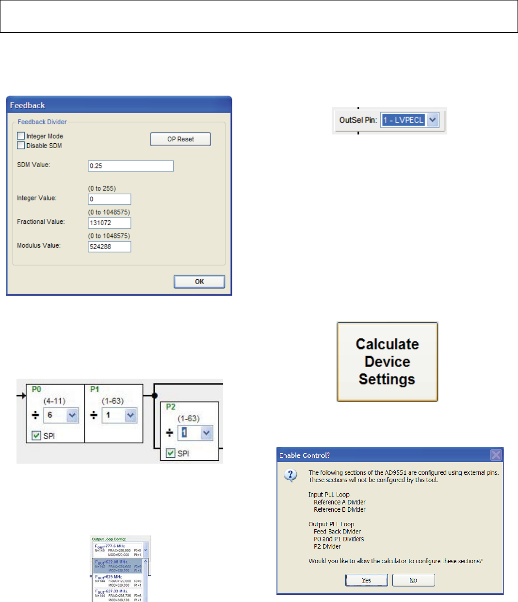
Feedback Window
Clicking Click for Details in the Feedback Divider box of the
main window accesses the Feedback window, which allows you
to change the feedback divider settings (see Figure 15).
08129-017
Figure 15. Feedback Window
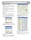
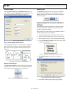
P0, P1, and P2 (Output Dividers) Boxes
Selecting the SPI check box in any of the divider settings boxes
(that is, the P0, P1, or P2 box) in the main window enables a
drop-down selection of predetermined divider settings (see
Figure 16).
08129-018
Figure 16. P0, P1, and P2 Boxes (in Main Window)
Output Loop Config: Box
The Output Loop Config: box can be used to change the output
frequency of the AD9551. This control changes the logic levels
of the output frequency selection pins of the AD9551.
08129-029
Figure 17. Output Loop Config: Box (in Main Window)
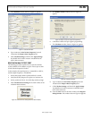
OutSel Pin: Box
The OutSel Pin: drop-down box (see Figure 18) in the main
window controls the logic level on the OUTSEL pin of the
AD9551. However, this value can be overwritten by using the
SPI control register.
08129-019
Figure 18. OutSel Pin Box (in Main Window)
USING SOFTWARE TO CALCULATE THE DEVICE
SETTINGS
The following procedure explains how the evaluation board
software can be used to automatically calculate and set the
settings to program the AD9551.
In this example, the input frequency is 122.88 MHz on REF A,
and the output frequency is 122.88 MHz.
1. Ensure that Jumper JMP3 is positioned for PC control.
2. Verify that all five jumpers are in place on Connector P2.
3. Set the positions of the S1, S2, and S3 dip switches to high.
4. Click Calculate Device Settings in the main window of the
evaluation board software.
08129-020
Figure 19. Calculate Device Settings Button (in Main Window)
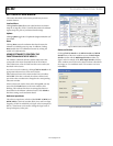
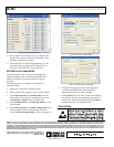
5. The Enable Control? window, shown in Figure 20,
appears.
08129-021
Figure 20. AD9551 Serial Port Programming Warning
6. Click Ye s to enable serial port register programming.