


UG-002 Evaluation Board User Guide
Rev. 0 | Page 8 of 12
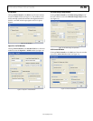
BUTTON BAR OF MAIN WINDOW
The buttons described in this section provide easy access to
common features.
Load and Save
Clicking Load and Save allows you to load and save an AD9551
setup file. A setup file (.STP) is a text file that contains the AD9551
register setup file, plus any evaluation board settings.
Update
Clicking Update toggles the I/O update bit (Register 0x05, Bit 0) of
the AD9551.
Reset
Clicking Reset resets the evaluation board and restores the
AD9551 to its default power-up state. In addition, clicking
Reset enables the VCO calibration function by writing the
enable VCO calibration bit.
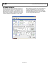
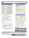
USING SOFTWARE TO CONTROL THE
FUNCTIONAL BLOCKS OF AD9551
The AD9551 evaluation software contains subsections that
correspond to the major functional blocks of the AD9551.
These subsections, most of which have their own window, are
described in this section.
You can access each window by clicking Click for Details in the
appropriate subsection box of the main window.
Most subsection boxes in the main window have a checkbox
labeled SPI. If this box is selected, the software allows serial
port writes when conditions are changed in the corresponding
subsection window.
When a subsection window closes after clicking OK, you may
notice that the LOAD button on the main window starts
blinking. This indicates that there are settings that have not
been loaded to the AD9551 evaluation board. Click LOAD to
load these settings to the evaluation board.
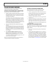
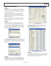
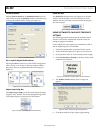
Reference Input Boxes
The reference input boxes, which are labeled REF A (MHz) and
REF B (MHz) in the main window, allow you to select an input
frequency for REF A and REF B (see Figure 9 for an example for
REF A). These boxes can be used to change the logic levels of
the input frequency select pins.
0
8129-009
Figure 9. REF A List Box (in Main Window)
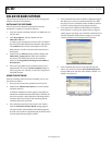
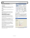
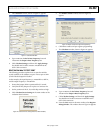
Reference Dividers
Clicking Click for Details in the REF A Divider and REF B
Divider boxes of the main window accesses the RefA Input
Divider window and the RefB Input Divider window (see
Figure 10 for an example of the RefA Input Divider window).
These windows are used to set the desired reference divider for
the integer or Σ- modulator mode. The counters can be set
individually.
08129-011
Figure 10. RefA Input Divider Window