


Evaluation Board User Guide UG-002
Rev. 0 | Page 5 of 12
GUIDE TO PROGRAMMING THE AD9551
The AD9551 can be programmed via an SPI port or by setting
the logic levels on the frequency select pins of the device. To
program the device using the serial port, the evaluation board
software must be installed.
For pin programming, there are two options: manually use the
dip switches or use the evaluation board software to override
the settings of the dip switches and change the logic levels of the
frequency select pins. Using the dip switches on the evaluation
board to establish the logic levels on the pins allows the AD9551
to power on with preset conditions. Alternatively, you can use
the software to override the settings of the dip switches on the
evaluation board and change the logic levels on the frequency
select pins.
USING AN SPI PORT
After the evaluation software is installed and the evaluation
board is connected to a PC and loaded with the software, the
following procedure can be used to configure and lock the PLLs.
In this example, the input frequency is 622.08 MHz on REF A,
and the output frequency is 622.08 MHz.
1. Ensure that Jumper JMP3 is positioned for PC control.
2. Verify that all five jumpers are in place on Connector P2.
3. Set the S1, S2, and S3 switches high. Set the S4 switch
setting to high, except for RESET, which must be set to low
(RESET is an active high pin).
These steps assume that the input signal is present, that the
evaluation board has not been modified, and that the PLL loop
filter is suitable for the application. However, this guide covers
only simple PLL operation (that is, to start and run the PLL).
For a detailed explanation of more advanced AD9551 features,
see the AD9551 data sheet. In addition, see the Software
Operation section.
USING DIP SWITCHES (MANUAL CONTROL)
The following procedure explains how the AD9551 can be pro-
grammed manually by using the dip switches on the evaluation
board to set the logic levels of the frequency select pins.
In this example, the input frequency is 622.08 MHz on REF A,
and the output frequency is 622.08 MHz.
1. Ensure Jumper JMP3 is positioned for manual control.
2. Verify that all five jumpers are removed on Connector P2.
3. Set the S1, S2, and S3 dip switch positions to low. (Note
that S2 controls REF B. If REF B is not used, there is no
need to change the S2 settings.).
4. Connect a signal generator to REF A SMA Connector J1.
By default, the reference inputs on this evaluation board
are ac-coupled and terminated 50 to ground.
5. Set the amplitude and frequency. An amplitude setting of
6 dBm is sufficient. Set the frequency to 622.08 MHz.
6. To connect a signal to REF B, connect the signal to SMA
Connector J2.
7. Connect an oscilloscope, spectrum analyzer, or other lab
equipment to any of the J3 to J6 SMA connectors on the
upper right side of the board.
8. Power the evaluation board by plugging it into the USB port.
9. A frequency of 622.08 MHz should be observed on the
OUT1 SMA connector.
If another input and/or output frequency is desired, remove
the USB port. Then change the dip switch settings, and
reapply the USB port connection.
After each dip switch setting, the AD9551 must be powered down
by removing the USB cable to reprogram the AD9551. See the
AD9551 data sheet for an explanation of pin programming.
USING SOFTWARE TO OVERRIDE DIP SWITCHES
(SOFTWARE CONTROL)
The evaluation board software can be used to override the
settings of the dip switches and apply a logic level to the
AD9551 frequency selection pins.
After the evaluation software is installed and the evaluation
board is connected to a PC and loaded with the software, the
following steps can be used to configure and lock the PLLs.
In this example, the input frequency is 622.08 MHz on REF A,
and the output frequency is 622.08 MHz.
1. Ensure that Jumper JMP3 is positioned for PC control.
2. Verify that all five jumpers are in place on Connector P2.
3. Set the S1, S2, and S3 dip switch positions to high.
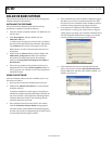
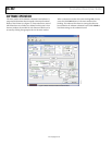
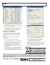
4. Select 622.08 MHz for the input frequency in the REF A
(MHz) box in the main window of the evaluation software
(see Figure 4 and the Reference Input Boxes section for
more information).
5. Select 622.08 MHz for the output frequency in the Output
Loop Config: box in the main window of the evaluation
software (see Figure 4).
6. A frequency of 622.08 MHz should be observed on the
OUT SMA connector.
These steps assume that the input signal is present, that the
evaluation board has not been modified, and that the PLL loop
filter is suitable for the application. However, these steps are
appropriate only for simple PLL operation (that is, to set up and
run the PLL). See the AD9551 data sheet for more information
about the various AD9551 features.