


Evaluation Board User Guide UG-002
Rev. 0 | Page 11 of 12
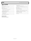
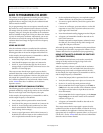
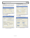
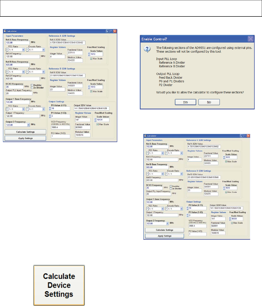
7. The Calculator window, shown in Figure 21, appears.
08129-022
Figure 21. Calculator Window
8. Type 122.88 into the Ref A Base Frequency: box and
122.88 into the Output 1 Base Frequency: box.
9. Click Calculate Settings, and then click Apply Settings.
You should now be able to measure 122.88 MHz at the
OUT1 SMA connector.
ROUTING 26 MHz TO TEST PORT
The following procedure explains how to route the 26 MHz
crystal oscillator to the AD9551 test port. The test port is SMA
J7 and is labeled output PLL locked.
In this example, the input frequency is 122.88 MHz on REF A,
and the output frequency is 122.88 MHz.
1. Ensure that Jumper JMP3 is positioned for PC control.
2. Verify that all five jumpers are in place on Connector P2.
3. Set the positions of the S1, S2, and S3 dip switches to high.
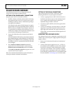
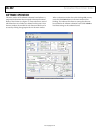
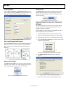
4. Click Calculate Device Settings in the main window of the
evaluation board software.
08129-023
Figure 22. Calculate Device Settings Button (in Main Window)
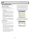
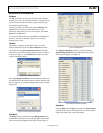
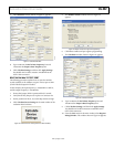
5. The Enable Control? window, shown in Figure 23,
appears.
08129-024
Figure 23. AD9551 Serial Port Programming Warning
6. Click Ye s to enable serial port register programming.
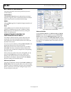
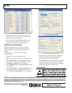
7. The Calculator window, shown in Figure 24, appears.
08129-025
Figure 24. Calculator Window
8. Type 122.88 into the Ref A Base Frequency: box and
122.88 into the Output 1 Base Frequency: box.
9. Click Calculate Settings, and then click Apply Settings.
You should now be able to measure 122.88 MHz at the
OUT1 SMA connector.
10. From the View menu in the main window, select Register
Debug Window. The window shown in Figure 25 appears.