


REV. A
Information furnished by Analog Devices is believed to be accurate and
reliable. However, no responsibility is assumed by Analog Devices for its
use, nor for any infringements of patents or other rights of third parties
which may result from its use. No license is granted by implication or
otherwise under any patent or patent rights of Analog Devices.
a
ADP1148, ADP1148-3.3, ADP1148-5
One Technology Way, P.O. Box 9106, Norwood, MA 02062-9106, U.S.A.
Tel: 781/329-4700 World Wide Web Site: http://www.analog.com
Fax: 781/326-8703 © Analog Devices, Inc., 1997
High Efficiency Synchronous
Step-Down Switching Regulators
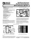
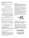
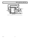
FUNCTIONAL BLOCK DIAGRAM
Q
R
S
V
TH1
V
IN
SENSE(–)
V
TH2
1.25V
OFF-TIME
CONTROL
100k⍀
13k⍀
B
V
IN
P-DRIVE SENSE(+) SENSE(–)
G
4 6
C
T
I
TH
SHUTDOWN
8
13
ADP1148
10mV to
150mV
C
V
FB
INT V
CC
REFERENCE
510
T
N-DRIVE
PWR
GND
14
12
ADJUSTABLE
VERSION
V
FB
9
7
S
1
Q
R
S
2
V
SLEEP
SIGNAL
GND
11
NON-OVERLAP
DRIVE
FEATURES
Operation From 3.5 V to 18 V Input Voltage
Ultrahigh Efficiency > 95%
Low Shutdown Current
Current Mode Operation for Excellent Line and Load
Transient Response
High Efficiency Maintained Over Wide Current Range
Logic Controlled Micropower Shutdown
Short Circuit Protection
Very Low Dropout Operation
Synchronous FET Switching for High Efficiency
Adaptive Nonoverlap Gate Drives
APPLICATIONS
Notebook and Palmtop Computers
Portable Instruments
Battery Operated Digital Devices
Industrial Power Distribution
Avionics Systems
Telecom Power Supplies
GPS Systems
Cellular Telephones
GENERAL DESCRIPTION
The ADP1148 is part of a family of synchronous step-down
switching regulator controllers featuring automatic sleep mode
to maintain high efficiencies at low output currents. These
devices drive external complementary power MOSFETs at
switching frequencies up to 250 kHz using a constant off-time
current-mode architecture.
V
IN
INT V
CC
I
TH
C
T
S-GND
P-DRIVE
SENSE(+)
SENSE(–)
SHUTDOWN
N-DRIVE
P-GND
ADP1148
++
P-CH
IRF7204
N-CH
IRF7403
1000pF
C
T
470pF
R
C
1k⍀
C
C
3300pF
C1
10BQ040
L*
62H
R
SENSE
**
0.05⍀
+C
OUT
390F
C
IN
100F
V
IN
(5.2V TO 18V)
1F
10nF
0V = NORMAL
>1.5V = SHUTDOWN
*COILTRONICS CTX-68-4
**KRL SL-1-C1-0R050L
V
OUT
5V/2A
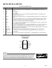
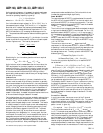
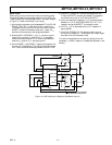
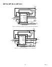
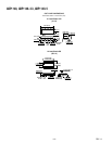
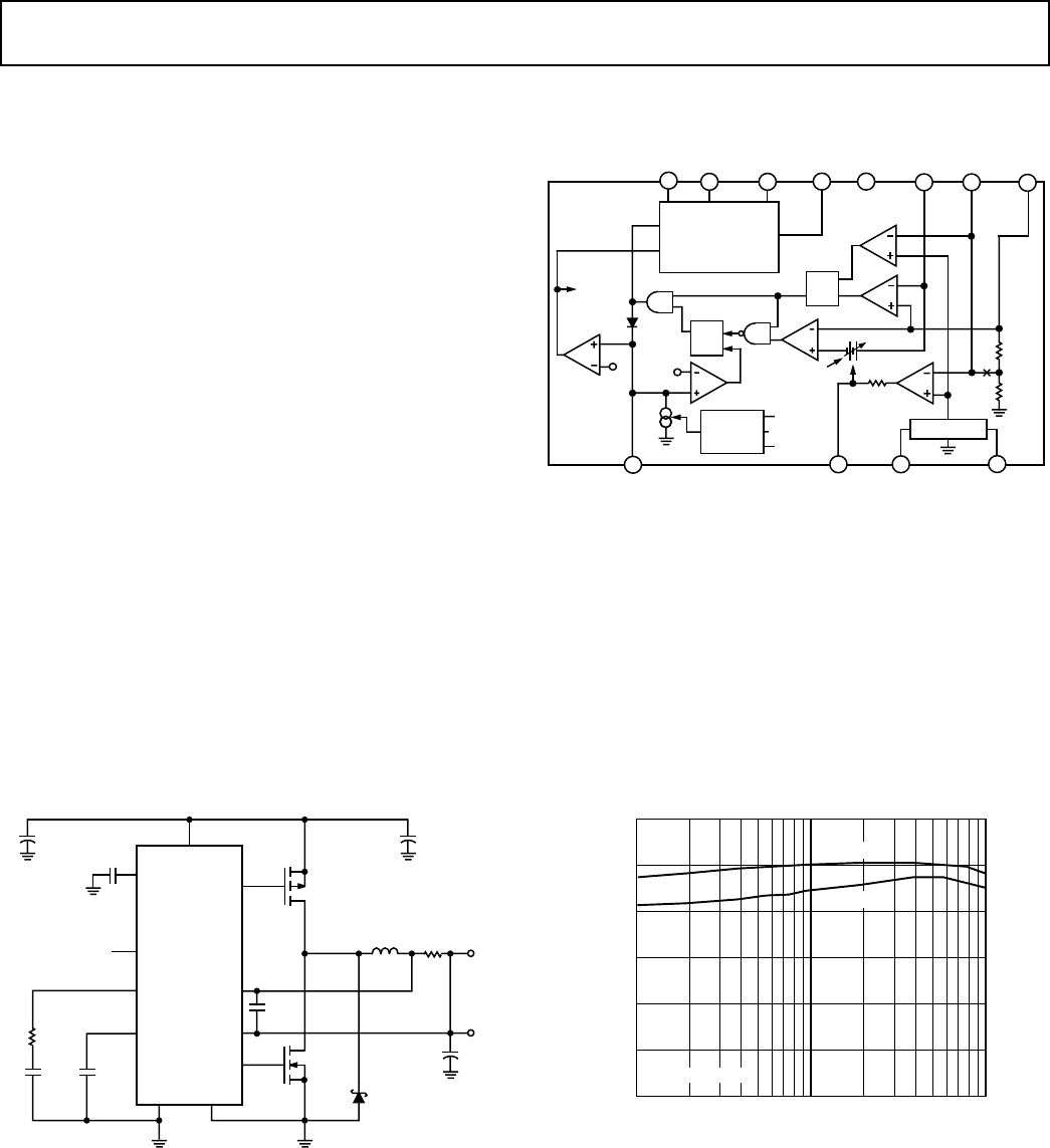
Figure 1. High Efficiency Step-Down Converter Figure 2. ADP1148-5 Typical Efficiency
The constant off-time architecture maintains constant ripple
current in the inductor, easing the design of wide input range
converters. Current-mode operation provides excellent line and
load transient response. The operating current level is user
programmable via an external current sense resistor.
The ADP1148 incorporates automatic Power Saving Sleep
Mode operation when load currents drop below the level re-
quired for continuous operation. In sleep mode, standby power
is reduced to only about 2 mW at V
IN
= 10 V. In shutdown,
both MOSFETs are turned off.
TYPICAL APPLICATIONS
LOAD CURRENT – A
100
85
70
0.02 2
95
90
80
75
EFFICIENCY – %
0.2
V
IN
= 6V
V
IN
= 10V
FIGURE 1 CIRCUIT