


ADP1148, ADP1148-3.3, ADP1148-5
–8–
REV. A
As the operating frequency is increased, the gate charge losses
will cause reduced efficiency (see Efficiency section). The full
formula for operating frequency is given by:
f = ( 1 – V
OUT
/V
IN
)/t
OFF
where t
OFF
= 1.3 × 10
4
× C
T
× V
REG
/V
OUT.
V
REG
is the desired output voltage (i.e., 5 V or 3.3 V), V
OUT
is
the measured output voltage. Thus, V
REG
/V
OUT
= 1 in regulation.
Note that as V
IN
reduces, the frequency also decreases. When
the input to output voltage differential drops below 1.5 V, the
ADP1148 reduces t
OFF
by increasing the discharge current in
C
T
. This prevents audible operation before the device goes into
dropout.
Once the frequency has been set by C
T
, the inductor L must be
chosen to provide no more than 25 mV/R
SENSE
of peak-to-peak
inductor ripple current. This is set by the equation:
25 mV
R
SENSE
=
V
OUT
× t
OFF
L
MIN
or
L
MIN
=
V
OUT
× t
OFF
× R
SENSE
25 mV
Substituting for t
OFF
from above gives the minimum required
inductor value of:
L
MIN
= 5.1 × 10
5
× R
SENSE
× C
T
× V
REG
As the inductor value increases above the minimum value, the
ESR requirements for the output capacitor are relaxed at the
expense of efficiency. If too small an inductor is used, the induc-
tor current will decrease past zero and change polarity. A result
of this occurrence will be that the ADP1148 may not be in
power saving mode operation and efficiency will be significantly
reduced at low currents.
Inductor Core
Once the minimum value for L is known, the selection of the
inductor must be made. High efficiency converters -π generally
cannot accommodate the core loss found in low cost powdered
iron cores, forcing the use of more expensive ferrite, molypermalloy
(MPP), or Kool Mµ
®
cores. Actual core loss is independent of
core size for a fixed inductor value, but it is very dependent on
inductance selected. As inductance increases, core losses de-
crease. Unfortunately, increased inductance requires more turns
of wire and therefore copper losses will increase.
Ferrite designs have very low core loss, so design goals can focus
on copper loss and preventing saturation. Ferrite core material
saturates “hard,” which causes the inductance to collapse
abruptly when the peak design current is exceeded. This results
in a sharp increase in inductor ripple current and subsequently
output voltage ripple which can cause the power saving mode
operation to be falsely triggered in the ADP1148. To prevent
this action from occurring, do not allow the core to saturate!
Molypermalloy from Magnetics, Inc., is a very good, low loss
core material for toroids, but it is more expensive than ferrite. A
reasonable compromise from the same manufacturer is Kool
Mµ. Toroids are very space efficient, especially when you can
use several layers of wire. Because they generally lack a bobbin,
mounting is more difficult. Many new designs for surface mount
components are also available from Coiltronics which do not
increase the component height significantly.
Power MOSFET
Two external power MOSFETs must be selected for use with
the ADP1148, a P-channel MOSFET for the main switch, and
an N-channel MOSFET for the synchronous switch. The main
selection parameters for the power MOSFETs are the threshold
voltage V
GS(TH)
and on resistance R
DS(ON)
.
The minimum input voltage dictates whether standard threshold
or logic-level threshold MOSFETs must be used. For V
IN
> 8 V,
standard threshold MOSFETs (V
GS(TH
) < 4 V) may be used. If
V
IN
is expected to drop below 8 V, logic-level threshold MOSFETs
(V
GS(TH)
< 2.5 V) are strongly recommended. When logic-level
MOSFETs are used, the ADP1148 supply voltage must be less
than the absolute maximum V
GS
rating for the MOSFETs (e.g.,
>±8 V of IRF7304.
The maximum output current I
MAX
determines the R
DS(ON)
requirement for the two power MOSFETs. When the ADP1148
is operating in continuous mode, the simplifying assumption can
be made that one of the two MOSFETs is always conducting
the average load current. The duty cycles for the MOSFET and
diode are given by:
P-Channel Duty Cycle = V
OUT
/V
IN
N-Channel Duty Cycle = (V
IN
– V
OUT
)/V
IN
From the duty cycle the required R
DS(ON)
for each MOSFET
can be derived:
P-Ch
RDS(ON)
= (V
IN
× P
P
)/[V
OUT
× I
MAX
2
× (1 + d
P
)]
N-Ch
RDS(ON)
= (V
IN
× P
N
)/[(V
IN
– V
OUT
) × I
MAX
2
× (1+d
N
)]
where P
p
and P
N
are the allowable power dissipations and d
p
and
d
N
are the temperature dependency of R
DS(ON)
. P
P
and P
N
will
be determined by efficiency and/or thermal requirements (see
Efficiency). (1+d) is generally given for a MOSFET in the form
of a normalized R
DS(ON)
vs. temperature curve, but d = 0.007/°C
can be used as an approximation for low voltage MOSFETs.
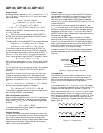
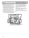
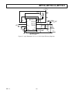
The Schottky diode D1 shown in Figure 1 conducts only during
the deadtime between the conduction of the two power
MOSFETs. D1’s purpose is to prevent the body-diode of the
N-channel MOSFET from turning on and storing charge during
the dead time, which could cost as much as 1% in efficiency. D1
should be selected for forward voltage of less than 0.5 V when
conducting I
MAX
.
C
IN
and C
OUT
Selection
In continuous mode, the source current of the P-channel
MOSFET is a square wave of duty cycle V
OUT
/V
lN
. To prevent
large voltage transients, a low ESR input capacitor sized for the
maximum rms current must be used. The maximum rms ca-
pacitor current is given by:
C
IN
required I
RMS
~ [V
OUT
(V
IN
– V
OUT
)]
0.5
× I
MAX
/V
IN
This formula has a maximum at V
IN
= 2 V
OUT
, where I
RMS
=
I
OUT
/2. This simple worst case condition is commonly used for
design because even significant deviations do not offer much
relief. Note that capacitor manufacturer’s ripple current ratings
are often based on only 2000 hours of life. This makes it advis-
able to further derate the capacitor, or to choose a capacitor
rated at a higher temperature than required. Several capacitors
may also be paralleled to meet size or height requirements in the
design. Always consult the manufacturer if there is any question.
All trademarks are the property of their respective holders.