


3.6 Using the Programmable Flag Pins
The ADSP-21535 has 16 asynchronous Programmable Flag (PF) I/O pins.
During reset PF0-PF9 function as inputs to the internal PLL of the DSP. They are
not valid until 120uS after reset. Table 3-3 describes how the PFs are used on the
EZ-KIT Lite.
After a DSP reset, all of the PF pins are initialized as inputs. The direction of the
PF is configured by the FIO_DIR Memory Mapped Register (MMR). The PFs
are set high (1) using the FIO_FLAG_S and cleared (0) using the FIO_FLAG_C
MMRs. For more information on configuring the PF pins, see the ADSP-21535
DSP Hardware Reference Manual.
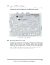
All of the PFs can are brought out to the expansion connector P2. The location of
the PF nets can be found in APPENDIX B: SCHEMATIC.
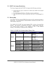
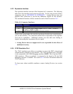
Table 3-3: Programmable Flag Pin Summary
Flag Connected
to
Use
PF0
LED4
PF1 LED1
PF2 LED2
PF3 LED3
PF0-3 are connected to the LEDs. These can be used
to light an LED when a routine completes.
PF4 SW4
PF5 SW5
PF6 SW6
PF7 SW7
PF4-7 are connected to the push buttons on the EZ-
KIT Lite board and are for user input. Your routine
can monitor and execute specific code when a push
button has been pressed.
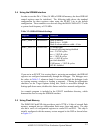
PF8 Not used
PF9 Not used
PF10 Not used
PF11 Not used
PF12 PMGMT0
PF13 PMGMT1
PF14 PMGMT2
These are used to change the internal voltage of the
DSP. Refer to section 3.6.1 for more information.
PF15 U7.11 Connected to the reset of the AD1885 Codec (U7).
This signal must be output as a high (1) to enable the
AD1885 Codec.
ADSP-21535 EZ-KIT Lite Evaluation System Manual
3-5