


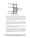
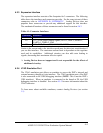
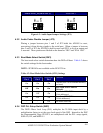
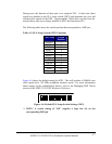
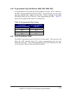
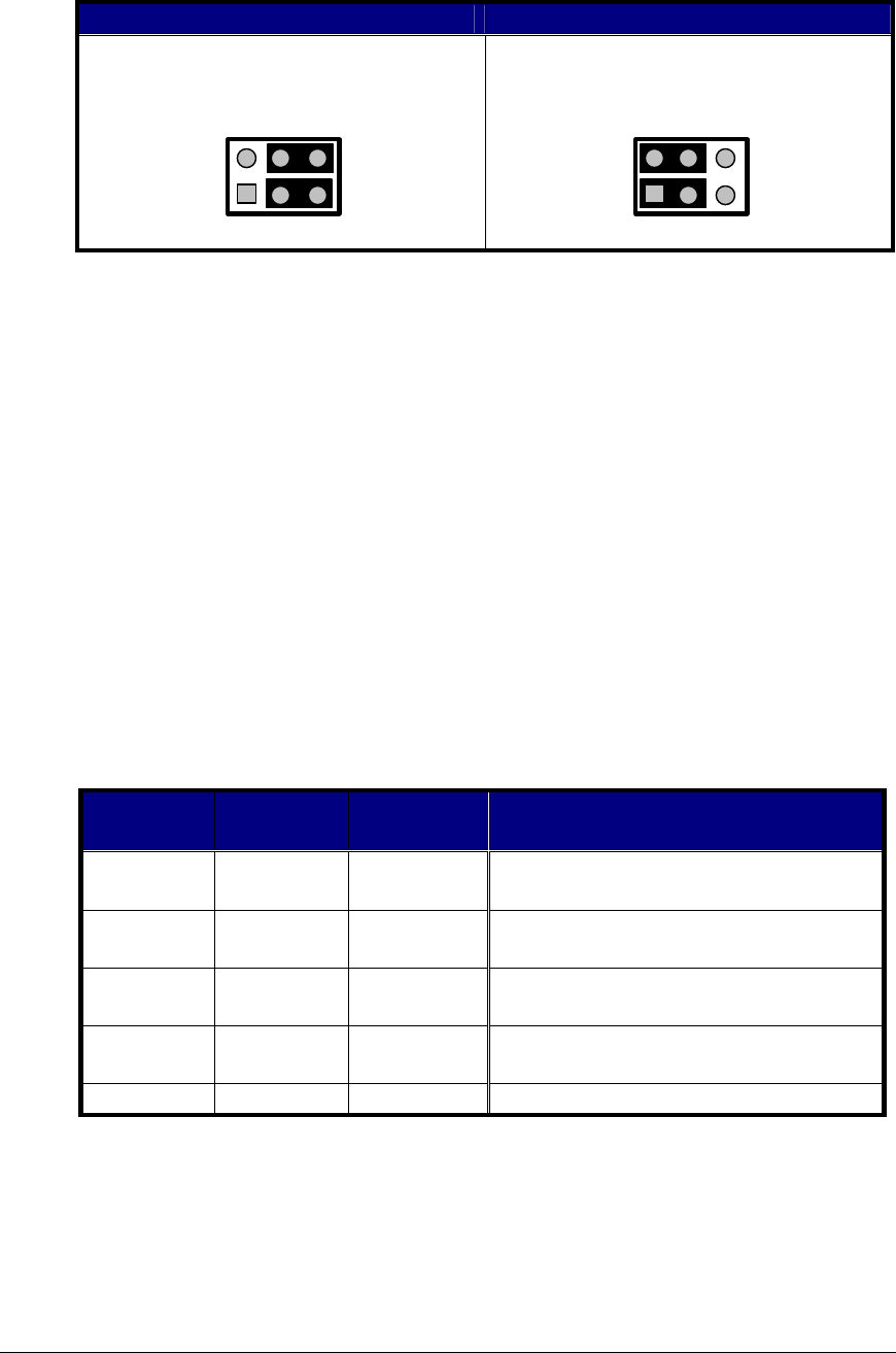
Stereo LINE_IN (DEFAULT)
Mono MIC1
MIC
JP1
LINE
2
1
6
5
MIC
JP1
LINE
2
1
6
5
Figure 4-3: Audio Input Jumper Settings (JP1)
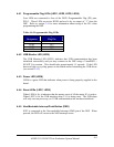
4.3.2 Audio Codec Disable Jumper (JP2)
Placing a jumper between pins 1 and 2 of JP2 holds the AD1885 in reset,
preventing it from driving signals to the serial port. When a jumper is between
pins 2 and 3 of JP2, the AD1885 is held in reset until PF15 is set to an output and
is asserted. These position are labeled on the board as “DIS” and “ENA 1885”.
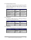
4.3.3 Boot Mode Select Switch (SW1)
The boot mode select switch determines how the DSP will boot. Table 4-2 shows
the switch settings for the boot modes.
NOTE: SPI ROM is not available on the EZ-KIT Lite.
Table 4-2: Boot Mode Select Switch (SW1) Settings
BMODE0
Pin 1
BMODE1
Pin 2
BMODE2
Pin 3
Function
On On On
Execute from 16 bit external memory
(no boot)
Off On On
Boot from 8-bit EPROM
(Default)
On Off On
Boot from SPI0 ROM
(8-bit addresses)
Off Off On
Boot from SPI0 ROM
(16-bit addresses)
- - Off All others reserved
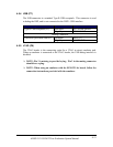
4.3.4 DSP PLL Setup Switch (SW2)
The DSP’s Phase Lock Loop (PLL) multiplies the 20 MHz input clock by a
multiplication factor to set the core clock speed of the DSP. Internal to the DSP
the Programmable Flags, PF0-PF9, are multiplexed with the PLL setup signals,
SSEL0-6, DF, and MSEL0-1.
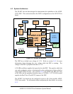
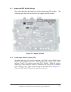
ADSP-21535 EZ-KIT Lite Evaluation System Manual
4-6