


7
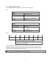
Pin
Signal
Names
Pin
Signal
Names
1
USB
Power
1
2
USB
Power
2
3
Negative
Signal
1
4
Negative
Signal
2
5
Positive
Signal
1
6
Positive
Signal
2
7
Ground
1
8
Ground
2
9
Key
(No
Connection)
10
Empty
Pin
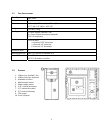
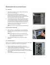
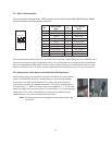
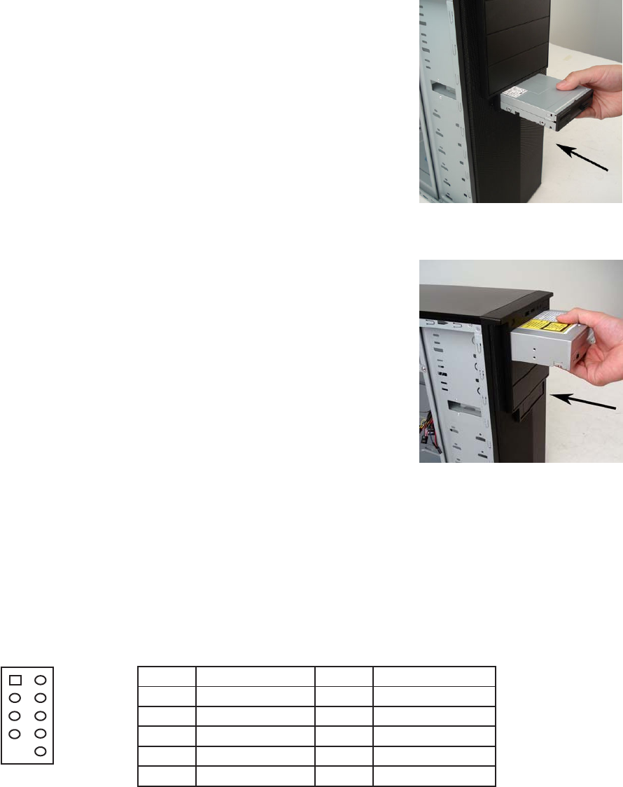
2.6 EXTERNAL3.5”DEVICEINSTALLATION
Thereisone3.5”drivebayavailablejustbelowthe5.25”drivebaysat
thefrontofthecase.Beforeyoubegin,removethesidepanelsand
frontbezelofthecaseasdescribedinsection2.1.
1. Slideyour3.5”deviceintothedrivebayfromthefrontand
align
thescrewholesonthedeviceswiththecorrespondingholesin
thechassis.
2. Fastenthedeviceinplacewiththeprovidedscrews.
3. Connecttheappropriatepoweranddatacables.
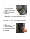
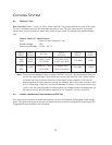
2.7
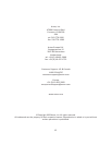
EXTERNAL5.25”DEVICEINSTALLATION
Therearethreeexternallyaccessible5.25”drivebays.Beforeyou
begin,removebothsidepanelsandfrontbezelasdetailedinsection
2.1.
1. Removethedrivebayfaceplatebyapplyingpressuretothe
insideoftheplateuntilitpopsfreeofthebezel.
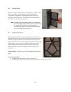
2. Slideyour5.25”device
intothebayfromthefrontofthecase.
3. Securethedriveintopositioninthedrivecageusingthe
providedscrews.
4. Mountanyother5.25”devicesaccordingly.
5. Connecttheappropriatepoweranddatacablestoyour
device(s).
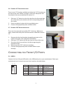
C
ONNECTINGTHE
F
RONT
I/O
P
ORTS
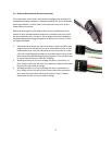
3.1USB2.0
ConnectthefrontI/OpanelUSBcabletotheUSBheaderpinonyourmotherboard.Checkyour
motherboarduser’smanualtoensurethatitmatchesthetablebelow:
12
910