


8
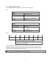
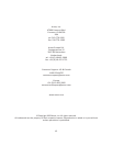
Pin
Signal
Names
(HDA)
Pin
Signal
Names
(AC’97)
1
MIC2
L
1
MIC
In
2
AGND
2
GND
3
MIC2
R
3
MIC
Power
4
AVCC
4
N
C
5
FRO-R
5
Line
Out
(R)
6
MIC2_JD
6
Line
Out
(R)
7
F_IO_SEN
7
N
C
8
Key
(no
pin)
8
Key
(no
pin)
9
FRO-L
9
Line
Out
(L)
10
LINE2_JD
10
Line
Out
(L)
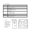
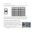
3.2AC’97/HDAUDIOPORTS
ThereisanIntel®standard10‐pinAC’97connectorandanIntel®10‐pinHDA(HighDefinitionAudio)
connectorlinkedtothefrontpanelofthecase.
10
6
4
2
9
7
5
3
1
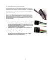
YoucanconnecteithertheAC’97ortheHDAconnector,dependingonyourmotherboard.
Locatetheinternalaudioconnectorsfrom yourmotherboardorsoundcardandconnect
thecorrespondingaudiocable.Consultyourmotherboardorsoundcardmanualforthe
pin‐outpositions.Evenifyoursystemsupportsbothstandards,only
useoneconnector.
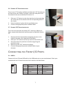
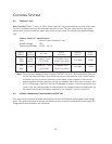
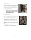
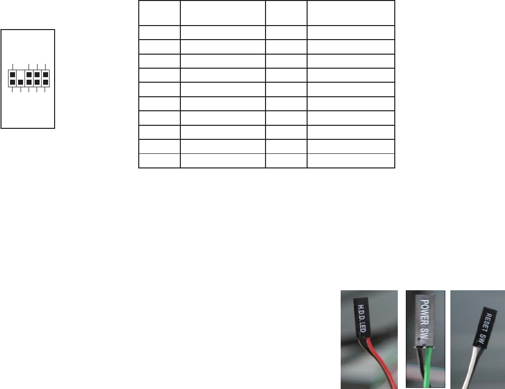
3.3
POWERSWITCH/RESETSWITCH/HARDDISKDRIVELEDCONNECTORS
ConnectedtoyourfrontpanelareLEDandswitchleadsforpower,
reset,andHDDLEDactivity.Attachthesetothecorresponding
connectorsonyourmotherboard.Consultyourmotherboard
manualforspecificpinheaderlocations. ForLEDs,coloredwires
arepositive(+). Whiteorblackwiresarenegative
(–).IftheLED
doesnotlightupwhenthesystemispoweredon,tryreversingthe
connection.FormoreinformationonconnectingLEDstoyour
motherboard,seeyourmotherboardmanual.
Note
:Polarity(positiveandnegative)doesnotmatterfor
switches.