


17
©1994 - INLINE, INC. IN1222 / IN1422 / IN1510 / IN1710 OPERATIONS MANUAL - REV. 2 12/04/99
COMMAND CODE STRUCTURE
All commands sent to the unit must contain a leading code, the command code, and an ending code.
Each command must be completely executed before the unit will accept a new command. When a
command is completed, the unit provides a response code; "OK" indicates the command was received
and executed,
"ERR" indicates there is a problem with the code and the command was not executed.
INLINE doublers and decoders can be set to recognize one of four sets of leading codes and ending
codes.
These are: [ ] { } ( ) < > . The factory default for leading / ending codes is [ ]. The unit can
only be set to a different command code by using an RS-232 command (see page 18).
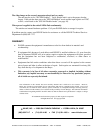
A complete command consists of:
[ The leading code
CH4 The command code. In this case CH4 would select the RGB input.
] The ending code
Sample command codes:
[CH1] Selects input 1
[GAM3] Selects Gamma Correction curve 3 for the current input channel
Controlling Multiple INLINE Products
INLINE products such as the Pathfinder, V-Net, the IN1222 / IN1240 / IN1422 doublers and the
IN1510 / IN1540 / IN1710 decoders use a similar communications protocol and command code
structure. By setting each unit to a different command code pair, up to four different INLINE products
can be controlled by a single RS-232 serial control port. Once a unit is set to look for a certain pair of
leading and ending delimiters (command codes), it will ignore all other commands sent by the port.
When daisy chaining multiple units together the 9-pin RS-232 control cable between the units must be
wired in parallel. The receive pin on all units must be connected together. Do not connect the transmit
pin between units.
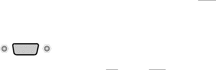
CONTROL PORT PIN-OUTS
The RS-232 control port is located on the rear panel just to the left of the power
switch. The control port uses a 9-Pin D male connector and the pin outs are:
Pin# Signal
2 Receive
3 Transmit
5 Ground