


34006451EN/AC - Page 13
Installation
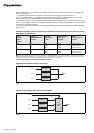
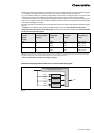
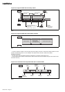
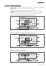
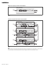
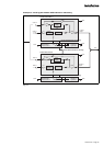
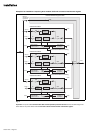
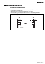
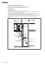
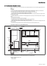
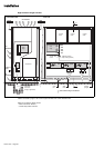
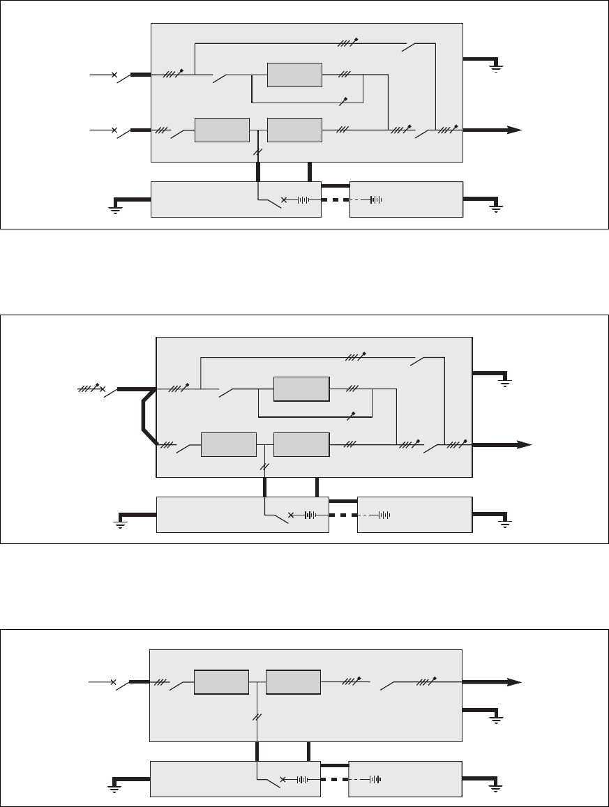
2.5 Power circuit wiring diagrams
Diagram for a single-unit or single modular UPS with common Mains 1 and 2
Diagram for a single-unit or single modular UPS with common Mains 1 and 2
Diagram for a frequency converter with batteries
The single-wire diagrams for typical UPS installations are given in figures 9 to 15. The heavy lines represent the cables that
must be connected
(see the table in the previous chapter for the required cross-sectional areas of the cables).
Note:
– for frequency converters, the input and output frequencies may be different (50 or 60 Hz);
– for frequency converters without batteries, ignore the battery cubicles and the + and - cables shown in the diagram.
Special case:
The UPSs can be optionally supplied with the neutral conductor not interrupted by switches Q4S, Q3BP and Q5N.
Fig. 9
Fig. 10
Fig. 11
mains 2
mains 1
static
switch
inverter
rectifier
charger
Q4S
Q3BP
load
battery cubicle
beside the
rectifier-inverter cubicle
earth
earth
+
-
+
-
other battery
cubicles (if
applicable)
frames interconnections for earthing
earth
QF1
Q1 Q5N
rectifier-inverter cubicle
static
switch
inverter
rectifier
charger
Q4S
Q3BP
load
battery cubicle
beside the
rectifier-inverter cubicle
earth
earth
+
-
+
-
other battery
cubicles (if
applicable)
frames interconnections for earthing
earth
QF1
Q1 Q5N
rectifier-inverter cubicle
mains 1
input
mains 2
input
mains
mains 1
inverter
rectifier
charger
load
battery cubicle
beside the
rectifier-inverter cubicle
earth
+
-
+
-
other battery
cubicles (if
applicable)
frames interconnections for earthing
earth
QF1
Q1 Q5N
rectifier-inverter cubicle
earth